1446
Simulation comparison of 28 different 31P arrays for cardiac MR spectroscopy at 7 T1Division MR Physics, Center for Medical Physics and Biomedical Engineering, Medical University of Vienna, Vienna, Austria, 2TUL (Technical University of Liberec), Liberec, Czech Republic, 3IKEM (Institute for Clinical and Experimental Medicine), Praha, Czech Republic
Synopsis
31P-MR spectroscopy measures cardiac energetics in vivo directly by means of ATP and PCr, but is limited due to low SNR due to the low MR sensitivity of the 31P nucleus and limitation by the achievable B1+. Comprehensive RF coil design considerations and planning help fully exploit the SNR gain by increase of B0. In this simulation study we compare 28 different 31P 7T RF coil array designs with respect to their transmit field performance and obtain a 3-channel array as the best variant.
Introduction
Cardiac phosphorous magnetic resonance spectroscopy (31P-MRS) has been shown to provide insight into cardiac energetics in vivo directly by means of ATP and PCr, but is limited by low SNR due to the intrinsic low MR sensitivity of the 31P nucleus. In addition, SNR is limited by the achievable flip angle, i.e the B1+ field of the transmitting RF coil [1]. Increasing B0 improves the quality of the acquired spectra, however, careful RF coil design and planning is required to fully exploit the achievable SNR. In this study we present an extensive comparison of suitable array designs for cardiac 31P-MRS to be integrated in an existing 1H cardiac array [2] at 7T via 3D electromagnetic simulation.Methods
Coil design: Suitable RF coil designs were intended to cover the average human heart size of 12x8x6 cm3 and its location approximately 2 cm below the sternum [3]. Additionally, the existing 1H coil housing and 12-channel layout [2] constrained the maximum number of elements, coil sizes, and shapes. Figure 1 shows all considered RF coil array configurations, ranging from 2- to 4-channel arrays differing in size and position, yielding a total number of 28 simulated arrays to be compared.
3D electromagnetic simulation (EMS): The coil designs were constructed in XFdtd 7.7 (Remcom, State College, PA, USA) using 1 mm thick wire, modeled as perfect conductor. All capacitors were replaced by 50Ω voltage sources to enable RF co-simulation in ADS (Keysight Technologies, Santa Rosa, CA, USA) [4]. All designs were simulated as overlap-decoupled arrays, where additional decoupling, when necessary, was achieved in RF co-simulation with counter-wound inductances. An overlap factor of 0.86 was used [5]. Realistic loss estimations for inductances, capacitances, and solder joints were modeled as series resistances. The array was loaded with a realistic human body model (“Duke”, Virtual Family, IT’IS Foundation, Zurich, Switzerland). Post-processing of 3D EM data and co-simulation results was performed in Matlab 2017b (Mathworks, Natick, MA, USA). To compare the performance of the designs, static B1+ shimming was obtained by varying the relative phase shift between the array elements in 5° steps for the 2- and 3- element arrays (72 and 5184 phase sets), and 10° steps for the 4 element arrays (46656 phase sets), respectively. The optimum was determined for each array by maximizing a merit function f that is a normalized and equally weighted combination of power efficiency (PE), SAR efficiency (SE), and relative homogeneity (RH) for a ROI comprising the heart lumen and muscle identified from the human body model:
$$\small \textbf{PE} = \frac{\overline{B_1^+}}{\sqrt{P_{in}}}, \hspace{0.5cm}\textbf{SE} = \frac{\overline{B_1^+}}{\sqrt{max(SAR_{10g})}},\hspace{0.5cm} \textbf{RH} = 1-\frac{std(B_1^+)}{\overline{B_1^+}},\hspace{0.5cm} \textbf{f}=\frac{1}{3}\left( \frac{PE}{max(PE)} + \frac{SE}{max(SE)}+\frac{RH}{max(RH)}\right)$$
where the maximum refers to the maximum encountered value within all simulated phase combinations for one array layout.
Choice of the best array: From the 28 B1+-shim optimized arrays, the best array was chosen by again calculating the merit function f, but with the maximum function in the formula referring to the maximum value encountered within the set of the 28 individually optimized arrays.
Results and Discussion
Matching for all elements was <
-55 dB, inter-element decoupling was always < -14 dB.
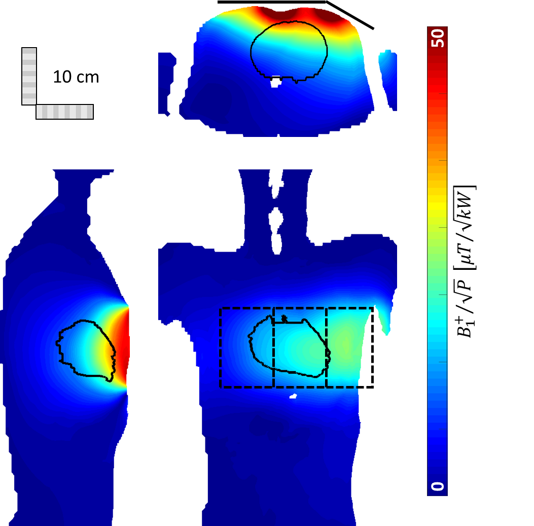
Fig. 2 summarizes the results for
the 28 individually optimized designs, together with the merit function f. The best design is the 3-channel
array with 9.4x14.1 cm² elements, centered above the heart, the corresponding B1+
maps are shown in Fig. 3. The optimal phase combination for this design
was 0°/-85°/-145°. The mean B1+ in the heart ROI was 23.4 µT/sqrt(kW)
and the
10-g maximum SAR was 0.49 kg-1.
Conclusion
In this work we present an extensive simulation study for the future implementation of a 31P RF coil array for cardiac phosphorous MRS at 7T resulting in a 3-channel design centered above the heart.Acknowledgements
This project was funded by the Austrian Science Fund (FWF) grants P28059-N36 and P28867-B30.References
[1] Valkovič et al. Using a whole-body 31P
birdcage transmit coil and 16-element receive array for human cardiac metabolic
imaging at 7T. PLoS One. 2017; 12(10): e0187153.
[2] Hosseinnezhadian S et al. A flexible 12-channel
transceiver array of transmission line resonators for 7 T MRI. J Magn Reson
2018; 296:47-59
[3] Gordon et al. Anatomy & Physiology. OpenStax 2013
[4] Kozlov M et al. Fast MRI coil analysis based on 3-D electromagnetic and RF
circuit co-simulation. J Magn Reson 2009; 200(1):147-52
[5] Mispelter et al. NMR Probeheads for Biophysical and Biomedical Experiments.
Imperial College Press 2006
Figures