1445
A 15-Channel Loop Dipole Array for In Vivo Swine Head MR Imaging at 10.5T1Biomedical Engineering, University of Minnesota Twin Cities, Minneapolis, MN, United States, 2Center for Magnetic Resonance Research (CMRR), University of Minnesota Twin Cities, Minneapolis, MN, United States, 3Recombinetics, St. Paul, MN, United States
Synopsis
Novel RF coil designs must address ultra high field MRI challenges and simultaneously exploit benefits thereof in terms of higher signal-to-noise ratio and reduced acquisition time. A 15-channel RF array was built composed of a 7-channel loop receive array and an 8-channel dipole transceiver array with the receive array designed to be scalable to high density arrays. Transmit B1 maps demonstrated transmit field immunity to receive array insertion. The absolute SNR generated by the loop array receiver is on average 2.65 times the absolute SNR of the dipole transceiver in locations near the receiver array. The coil was successfully used in combination with dipole transceivers to acquire in-vivo swine brain anatomical images at 10.5T.
Introduction
In recent years, the effort to move to ultra high fields (UHF) in MRI has introduced additional design challenges as well as opportunities for RF coils [1]. At such ultra high fields, incorporating high density receive arrays in RF coil design is shown to significantly improve SNR [2-3].
In the current study, a 7-channel receive array is built and used to improve SNR in in-vivo swine head MR imaging at 10.5T. Successful acquisitions with this coil were a proof-of-principle milestone in the road to develop high density receive arrays for human head imaging at 10.5T.
Methods
Preamplifier and overlap decoupling techniques were used in the receive array design to minimize cross-talk between loop elements [4]. PIN diode detuning circuits were incorporated at the feed point of each receive element.
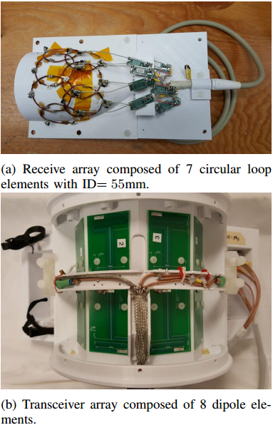
The 7-channel receive array, shown in Figure 1a, was incorporated into an 8-channel dipole transceiver [5], shown in Figure 1b. A major improvement towards the desired high density arrays was the development and integration of small preamp boards utilizing a proprietary low noise preamplifier (WanTcom, WMA447A, Minneapolis, MN) with an input impedance of 1.5 ohms and noise figure of 0.45 dB (See Figure 1a). The preamplifiers were stacked close together, in a configuration representative of their arrangement in upcoming high-density human head coils, to allow for evaluation of their reliability and potential crosstalk. Furthermore, low loss semi-rigid coaxial cable was used to connect the preamps to the coils, thus minimizing resistive losses and maximizing preamp decoupling.
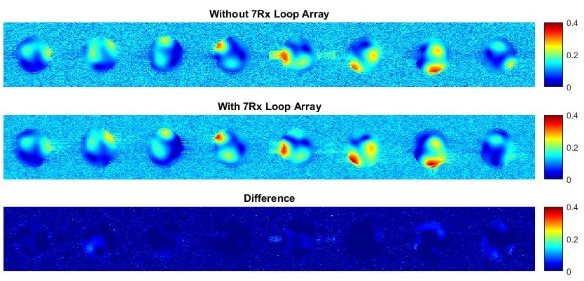
As an additional safety mechanism, passive detune circuits, implemented using fast-switching crossed-pair diodes (UMX9989AP, Microsemi, MA, USA) in each loop, are switched to the conducting state during transmit, effectively opening the loop as an inductor resonates in parallel with a segmentation capacitor. Relative transmit B1 maps were obtained by collecting small flip angle multislice gradient echo (GRE) images with only one channel transmitting at a time, each magnitude image being then divided by the sum of the magnitudes of the individual transmit channel images [6].
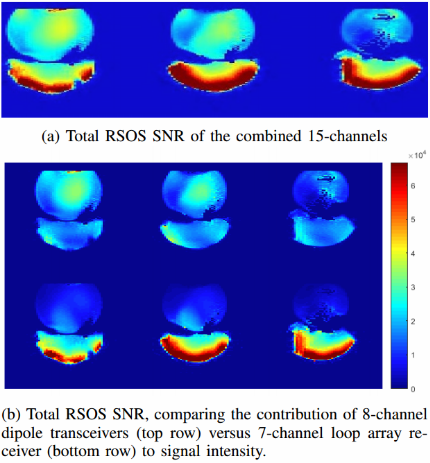
In order to generate SNR maps, a fully relaxed transverse multislice gradient echo (GRE) image was acquired with nominal flip angle=80°, TR=7000 ms, TE=4 ms, bandwidth=300 Hz/px, followed by a noise scan (same as SNR scan, FA=0°, TR=140 ms), using a phantom composed of a saline sphere directly on top of a saline bag placed on the receiver array.
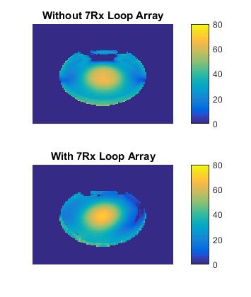
An absolute B1+ map was obtained with a 3D AFI [7] acquisition (TR1/TR2=20ms/120ms, nominal flip angle 80°) normalized by sin(α(r)) of the signal obtained with the former GRE sequence were α(r) is the flip angle and r the spatial coordinate [8]. The GRE signal was decorrelated between receive channels based on the complex noise dataset. The final SNR was obtained with the root sum of squares of the individual channel SNR.
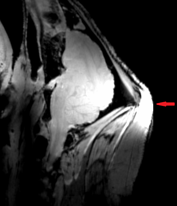
Finally, the coil was used to acquire in-vivo swine brain images at 10.5T.
Results
Relative transmit field per channel, presented in Figure 2, and absolute |B1+| maps with all channels transmitting together with CP-like mode transmit phase distribution, presented in Figure 3, for a phantom in the presence of and in the absence of receive array indicate that very limited transmit field variation occurred when inserting the receive array in the transmit array, hence corroborating effective detuning of the receive circuitry.
Absolute signal-to-noise ratio maps, presented in Figure 4, demonstrate the SNR contribution from the 7-channel surface loop array. The average SNR contribution of the loop array in the saline bag is 2.65 times the SNR contribution of to the dipole transceivers. The SNR of the loop array is comparable to that of the dipole array at the center of the phantom.Furthermore, in-vivo parallel transmit swine brain imaging, presented in Figure 5, demonstrates successful implementation of the coil.Discussion
We have successfully built a customized piglet head RF coil array which allowed the simultaneous acquisition with a volume coverage 8-channel dipole transceiver array and a half-volume 7-channel loop receive-only array. In this initial design, the receive array was built to cover only the upper part of the swine head (closest to the animal's brain) but future work will expand this to whole head coverage.
This work demonstrates the feasibility of combining our receive array technology with transceiver dipoles and is an important step towards higher channel count arrays in the future. Reliable performance of preamplifier boards and scalability to a closely stacked configuration were demonstrated in this work. We will expand to high-density human head receive arrays using the design tested in this work as our building block.
Acknowledgements
The authors acknowledge NIH S10 RR029672, NIH U01EB025144, BTRC P41 EB015894, P30 NS076408, and NIH R34AG055178 grants.References
[1] Van de Moortele PF, Akgun C, Adriany G, Moeller S, Ritter J, Collins CM, Smith MB, Vaughan JT, Ugurbil K. B1 destructive interferences and spatial phase patterns at 7T with a head transceiver array coil. MagnReson Med 2005; 54:1503-1518.
[2] Shajan, G. , Kozlov, M. , Hoffmann, J. , Turner, R. , Scheffler, K.and Pohmann, R. (2014), A 16-channel dual-row transmit array in combination with a 31-element receive array for human brain imaging at 9.4 T. Magn. Reson. Med., 71: 870-879. doi:10.1002/mrm.24726
[3] Boris Keil, Lawrence L. Wald, Massively parallel MRI detector arrays, Journal of Magnetic Resonance, Volume 229, 2013, Pages 75-89,https://doi.org/10.1016/j.jmr.2013.02.001.
[4] P.B. Roemer, W.A. Edelstein, C.E. Hayes, S.P. Souza, O.M. Mueller The NMR phased array, Magn. Reson. Med., 16 (1990), pp. 192-225
[5] RL Lagore, L DelaBarre, J Radder, N Harel, E Yacoub, EJ Auerbach, G Adriany. An 8-CH Dipole Tranceive and 8-CH Loop Receive Array for Head Imaging of Non-Human Primates at 10.5T. ISMRM 2018; p. 1747.
[6] Van de Moortele, P. F., Snyder, C., DelaBarre, L., Adriany, G., Vaughan, J. T. and Ugurbil, K. Calibration Tools for RF Shim at Very High Field with Multiple Element RF Coils: from Ultra Fast Local Relative Phase to Absolute Magnitude B1+ Mapping. in Proc Intl Soc Mag Reson Med. Berlin, (2007) p 1676.
[7] Yarnykh, V. L. Actual flip-angle imaging in the pulsed steady state: a method for rapid three-dimensional mapping of the transmitted radio frequency field. (2007) Magn Reson Med 57, 192-200.
[8] Adriany, G. , Van de Moortele, P. , Wiesinger, F. , Moeller, S. , Strupp, J. P., Andersen, P. , Snyder, C. , Zhang, X. , Chen, W. , Pruessmann, K. P., Boesiger, P. , Vaughan, T. and Uğurbil, K. (2005), Transmit and receive transmission line arrays for 7 Tesla parallel imaging. Magn. Reson. Med., 53: 434-445.
Figures