1444
Shielded hybrid coil array1College of nuclear equipment and nuclear engineering, Yantai University, Yantai, China, 2Institute of Imaging Science, Vanderbilt University, Nashville, TN, United States, 3Department of Radiology and Radiological Sciences, Vanderbilt University, Nashville, TN, United States, 4Department of Biomedical Engineering, Vanderbilt University, Nashville, TN, United States
Synopsis
Two major factors that limit the performance of Rx coil arrays are restrictions on coil geometry and numbers. For the widely used L/C loop array, each loops’ size has to be reduced to achieve an increased number of coils. An alternative approach is to use hybrid coils which combine loops with other resonator shapes such as a figure-of-8 coil, butterfly coil, microstrip or dipole. However, the coupling between elements in hybrid coil arrays proves to be challenging due to the proximity of more coil elements. To solve this problem, we propose a novel design named “shielded hybrid coil” which combines hybrid loop+figure-of-8 resonators with circumferential shielding. We proposed two kinds of shielded hybrid resonator arrays (inner- or outer-pick-up) that exhibit an obvious Rx-performance improvement compared to conventional loop arrays. We also find that the Rx-performance is better with outer-pick-up.
Introduction:
Two
major factors that limit the performance of receiver (Rx) coil arrays are
restrictions on coil geometry 1
and numbers. For the widely used L/C loop array, each loops’
size has to be reduced to achieve an increased number of coils 2. An
alternative approach is to use hybrid coils which combine loops with other
resonator shapes such as a figure-of-8 coil, butterfly coil, microstrip or
dipole 3-6. However, the coupling between elements in hybrid coil
arrays proves to be challenging due to the proximity of more coil elements. To
solve this problem, we propose a novel design named “shielded hybrid coil”
which combines hybrid loop+figure-of-8 resonators with circumferential shielding
7-9.Methods:
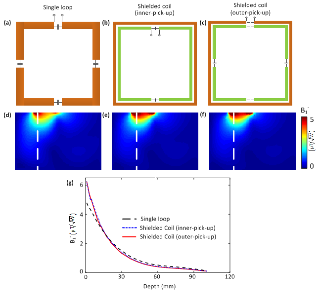
Circumferential shielding is an easy-to-build approach to reduce the mutual coupling between adjacent loop elements. It consists of a two-ring structure where the inner resonator is used as the pick-up coil (referred to as inner-pick-up) and the outer shielding is passive. The basis for its decoupling capability is that the two rings operate in differential-mode (with opposite currents) which confines its magnetic field to the local area. Therefore, if the outer shielding is used as the pick-up coil and the inner resonator passive (referred to as outer-pick-up), their low coupling should be maintained. Figures 1a-c show schematics of a single loop, an inner-pick-up shielded loop and an outer-pick-up shielded loop, respectively. Figures 1d-1f show their axial receive B1 ( B1-) fields on a water phantom (dimension 10×20×10 cm3, б=0.6 S/m and ξr=78, placed 0.5 cm below coils). Both the inner- and outer-pick-up coil have a confined field which ensures low inter-element coupling and improves the surface SNR at the expense of slightly lower SNR in the deeper area (Figure 1g). Both coils will be further used for hybrid resonators.
For both the inner- and outer-pick-up shielded loops (Figures 1b-c), the outer/inner ring has a dimension of 5.5×5.5 cm2/4.9×4.9 cm2; the conductor width is 2 cm and the gap between two rings is 1 mm. Simulations were performed using HFSS (ANSYS, Canonsburg, PA, USA). In all simulations, coil elements were tuned to the Larmor frequency of 7T (298 MHz) and matched to 50 Ω.
Results and Discussions:
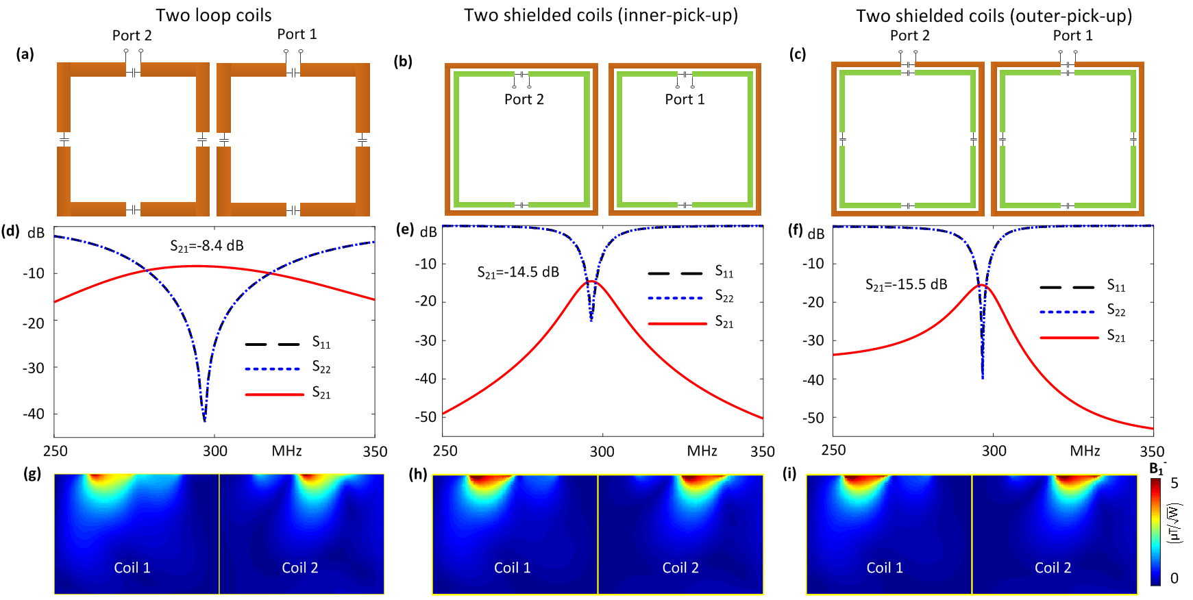
Figures 2a-c show schematics of two loops without the shielding, two inner-pick-up shielded loops and two outer-pick-up shielded loops. When two loops are placed side by side without any shielding, they couple to each other (S21 =-8.4 dB, Figure 1d) and considerable B1- field decreases are observed (Figure 2g vs. Figure 1d). For either the inner- or outer-pick-up structures, the mutual coupling is much lower (S21<-14.5 dB) and the original B1- field is preserved (Figures 2h-i vs. Figures 1e-f).
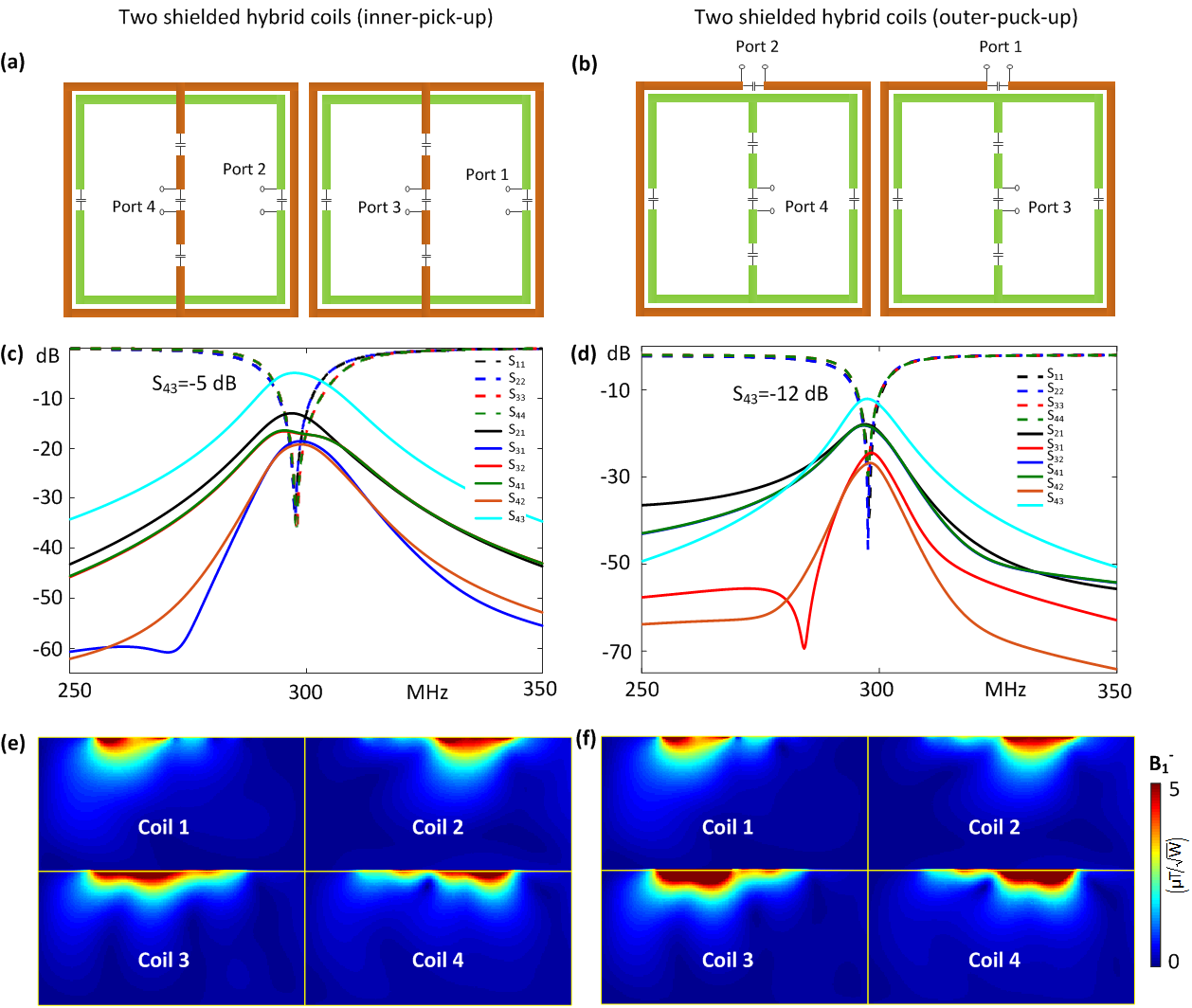
The outer-pick-up coil described has almost the same performance as the conventional inner-pick-up coil. However, they may be distinguished if we move to a quadrature design by adding another resonant mode. For the inner-pick-up coil, the outer conductor is used as part of a figure-of-8 (Fo8) coil. For the outer-pick-up coil, the inner resonator forms a hybrid resonator with two resonant modes: the loop mode and the Fo8 mode. The loop mode is still pick-up by the outer ring (ports 1-2 in Figure 3b), while the Fo8 mode is pick-up by the middle conductor (ports 3-4 in Figure 3b). In either inner- or outer-pick-up designs, the outer ring still performs a shielding effect, which ensures isolation between coil 1 and coil 2 better than -14 dB (Figures 3c-d). However, strong coupling (-5 dB) between two adjacent Fo8 coils (coil 3 and coil 4) is observed for the inner-pick-up design, whereas this isolation still reaches -12 dB for outer-pick-up coils.
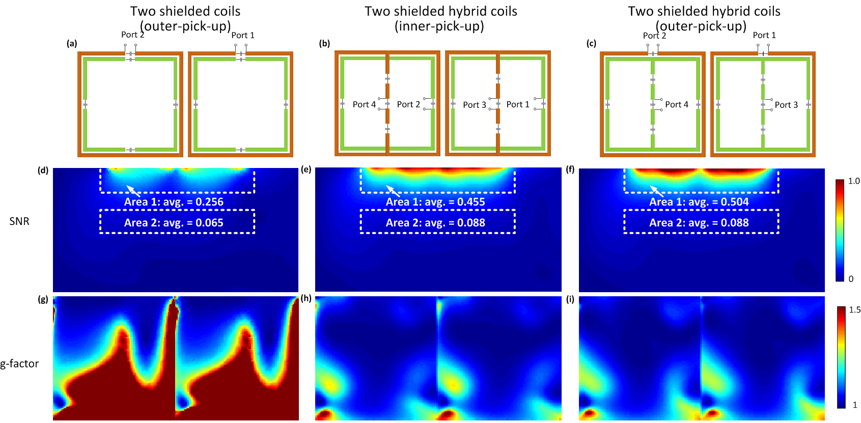
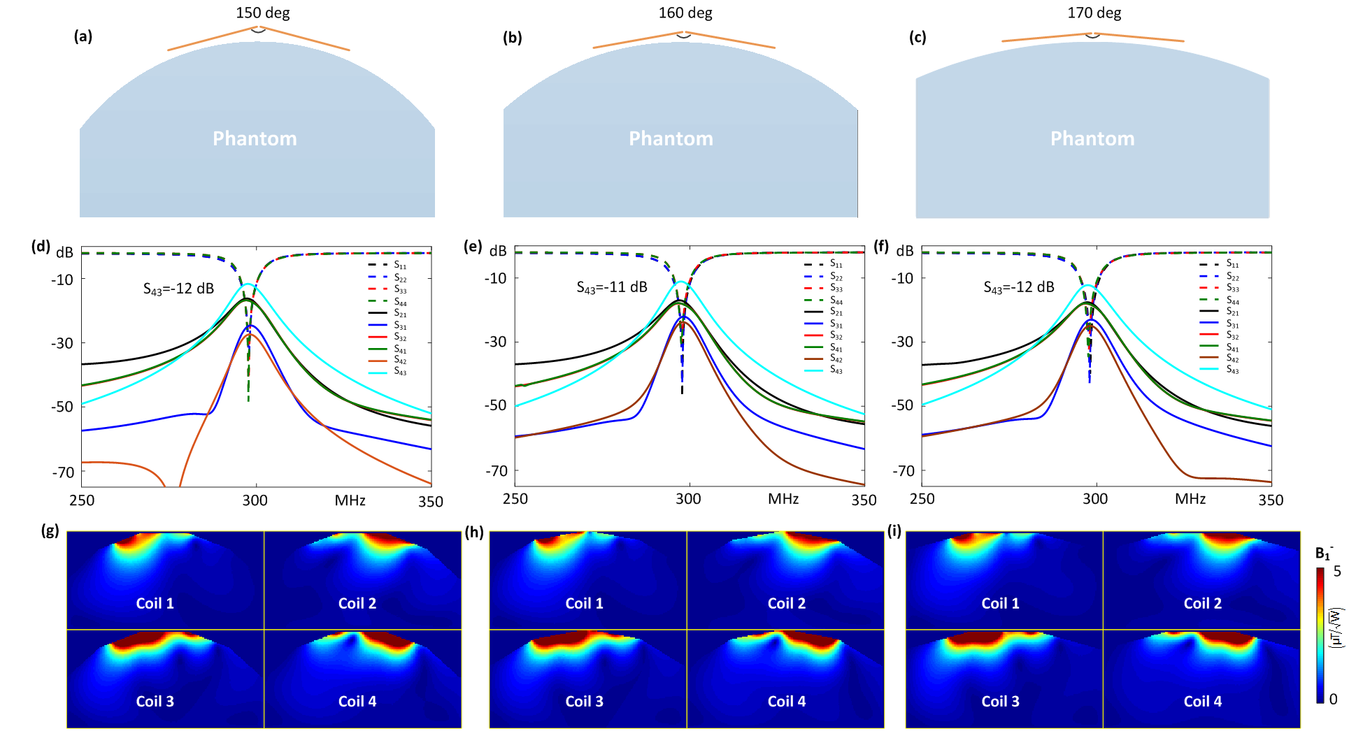
Figure 4 shows the SNR and g-factor comparison between two shielded coils (Figure 4a) and two shielded hybrid coils with inner-pick-up (Figure 4b) and two shielded hybrid coils with outer-pick-up (Figure 4c). Compared to the non-hybrid coils, the hybrid coils have obvious SNR improvement, by 1.6 times with inner-pick-up and 2.1 times with outer-pick-up at the surface area and SNR improvement by 35% in the deep area. Due to the increased coil number, the hybrid coil array has much lower g-factor, as shown in Figures 4g-i. As demonstrated by the previous work7, the circumferential shielding has robust decoupling performance for modular and flexible coil designs. This was also validated in a hybrid design where the isolation can be maintained in different bending conditions (Figure 5).
Conclusion:
We proposed
two kinds of shielded hybrid resonator arrays (inner- or outer-pick-up) that exhibit an obvious Rx-performance
improvement compared to conventional loop arrays. We also find that the
Rx-performance is better with outer-pick-up. Acknowledgements
Dr. Ming Lu's work was supported by Natural Science Foundation of Shandong Province (ZR2016AQ02)References
1. Roemer, P. B., Edelstein, W. A., Hayes, C. E., Souza, S. P. and Muelle, M. (1990), The NMR phased array. Magn. Reson. Med., 16: 192–225. doi: 10.1002/mrm.1910160203.
2. Wiggins, G. C., Triantafyllou, C., Potthast, A., Reykowski, A., Nittka, M., and Wald, L. L. (2006), 32-channel 3 Tesla receive-only phased-array head coil with soccer-ball element geometry. Magn. Reson. Med., 56: 216-223. doi:10.1002/mrm.20925.
3. Kumar, A. and Bottomley, P. A. (2008), Optimized quadrature surface coil designs. Magn. Reson. Mater. Phy., 21: 41–52. doi: 10.1007/s10334-007-0090-2.
4. Guclu, C. C., Boskamp, E., Zheng, T., Becerra, R., & Blawat, L. (2004), A method for preamplifier-decoupling improvement in quadrature phased-array coils. J. Magn. Reson. Imaging, 19: 255-258. doi: 10.1002/jmri.10449.
5. Zhang, X., Ugurbil, K. and Chen, W. (2001), Microstrip RF surface coil design for extremely high-field MRI and spectroscopy. Magn. Reson. Med., 46: 443–450. doi: 10.1002/mrm.1212.
6. Lattanzi, R., Wiggins, G. C., Zhang, B., Duan, Q., Brown, R., & Sodickson, D. K. (2018), Approaching ultimate intrinsic signal-to-noise ratio with loop and dipole antennas. Magn. Reson. Med., 79: 1789-1803. doi: 10.1002/mrm.26803.
7. T. Lanz, and M. Griswold, “Concentrically shielded surface coils – A new method for decoupling phased array elements,” in Proc. 14th Annu. Meeting ISMRM, Seattle, 2006, pp. 217.
8. Belliveau, J., Gilbert, K. M., Abou-Khousa, M. and Menon, R. S. (2013), Analysis of circumferential shielding as a method to decouple radiofrequency coils for high-field MRI. Concept. Magn. Reson. B, 43: 11-21. doi: 10.1002/cmr.b.21227.
9. Yeh, J. T., Lin, J. L., Li, Y. and Lin, F. (2018), A flexible and modular receiver coil array for magnetic resonance imaging. IEEE TMI. doi: 10.1109/TMI.2018.2873317.
Figures