1440
A MRI Gradient Induced Electric Field Exposure System for Active Implanted Medical Devices1Abbott Laboratories, Sylmar, CA, United States
Synopsis
MRI gradient field can produce electric field (E-field) in a patient during MR scan. For patient with active implanted medical device (AIMD), damage and malfunction are the possible outcomes due to such exposure. The ISO/TS 10974 radiated immunity test method in Clause 16 focuses on producing radiated gradient field (dB/dt) exposure. This abstract proposes a test method which directly exposes AIMD to gradient frequency E-field, offering a controlled gradient frequency E-field exposure environment for AIMD MR conditional testing.
Introduction
For a patient with active implanted medical device (AIMD), the gradient magnetic fields in a MR scanner will induce electric field (E-field) in the patient, which in term produces voltage drop across the AIMD. The induced voltage may adversely affect device function and/or cause device damage. ISO/TS 10974 recommends radiated gradient immunity test for AIMD1. The test method in ISO/TS 10974 offers guidance to generate radiated dB/dt field for device exposure. As noted by the standard, the E-field that can be achieved is limited by the radius of a circular phantom. Hence, applying radiate dB/dt exposure is not well suited for testing AIMD under the influence of gradient induced voltage. In this abstract, a supplementary test method which directly exposes an AIMD to gradient frequency E-field without the need of generating dB/dt field, is introduced.Methods
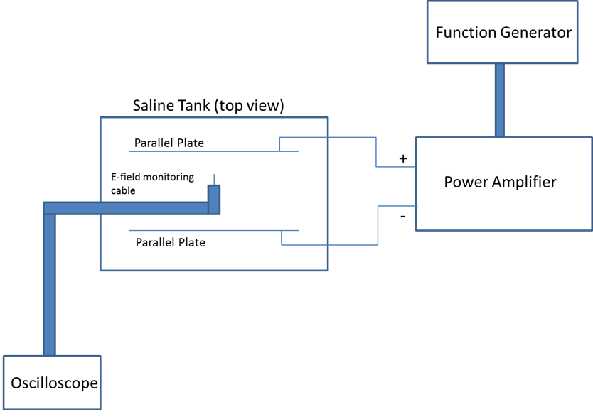
The top-level block diagram of the exposure system is shown in Figure 1. To produce a controlled E-field exposure environment, a pair of conductive parallel plates are submerged in saline which simulate the tissue environment around the AIMD. The conductivity of saline is determined by the tissue type in the region where AIMD is implanted. The low frequency tissue property database2 provided by IT’IS foundation can be applied for tissue conductivity at MR gradient field frequency. A power amplifier is used to control the voltage difference between the parallel plates, while an E-field is generated between the parallel plates. As the external E-field and the induced voltage on AIMD electrodes exhibit linear relationship, the desirable induced voltage level can be obtained by controlling the external E-field level.
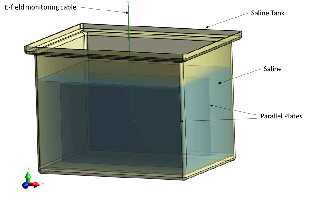
To adjust the external E-field level, a monitoring cable is designed to measure the E-field level in the exposure region. The cable is essentially a coaxial cable, with its inner conductor extended out, followed by a small insulation gap between the inner conductor and outer conductor. This allows the cable to pick up any difference in the scalar potential field. When the monitoring cable is exposed to an incident E-field, a voltage difference is captured by an oscilloscope. A conversion factor is needed to translate the measured voltage difference to the incident E-field. Sim4Life3 electro-quasi-static (EQS) solver were employed to design the test set up (plates dimensions and phantom size) and the monitoring cable through simulations (see Figure 2). Based on the simulated design, a hardware prototype was constructed.
Per guidance from IEEE Std 1309™-20134, the simulated E-field distribution between the parallel-plates and the conversion factor were compared to the actual measurement. The difference was found to be within 10% between simulation and measurement. To perform an exposure test, the time-domain waveform for the E-field shall follow the dB/dt waveform recommended in ISO/TS 10974 Clause 16. The in vivo E-field level shall be determined per ISO/TS 10974 Annex A, based on AIMD size, implant site and MR conditional labelling specifications.
Results
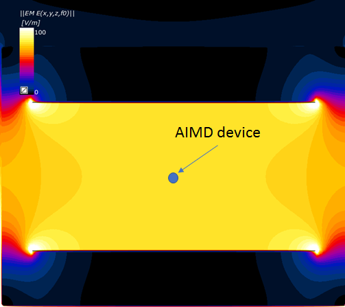
Figure 2 shows the parallel plate system simulated in Sim4Life. The dimension of the parallel plate is 50 cm by 30 cm and the distance between the parallel plates is 26 cm. Figure 3 shows the incident E-field distribution with a 20 V voltage difference between the parallel plates in saline environment.Discussion
Figure 3 shows that a significant E-field region between the parallel plate is homogenous and can be used for exposure. An example of test setup is also shown in Figure 3. An AIMD device (represented by a point in Figure 3) are placed inside the homogenous E-field region so that a radiated gradient induced voltage test can be performed using the proposed set up.Conclusion
A MR gradient induced E-field exposure test system is developed based on parallel plate structure. The proposed test system supplements the existing ISO/TS 10974 2018 radiated gradient immunity test and allows the exposure of AIMDs to gradient frequency E-field without the need of generating gradient magnetic field (dB/dt).Acknowledgements
No acknowledgement found.References
1. ISO/TS 10974 Assessment of the safety of magnetic resonance imaging for patients with an active implantable medical device
2. https://itis.swiss/virtual-population/tissue-properties/database/low-frequency-conductivity/
3. https://www.zurichmedtech.com/sim4life/
4. IEEE Std 1309™-2013 IEEE Standard for Calibration of Electromagnetic Field Sensors and Probe (Excluding Antennas) from 9 kHz to 40 GHz
Figures