1424
Feasibility of bright-bone cervical spine MRI using Zero TE sequence at 3T1Radiology, Mayo Clinic, Rochester, MN, United States, 2Siemens Healthcare, Rochester, MN, United States
Synopsis
Direct visualization of solid cortical bone structures with MRI is gaining increased interest. “Bright-bone” techniques based on ultrashort echo time (UTE) and Zero TE (ZTE) sequences enable obtaining signals from the cortical bone and are thus desirable for visualizing cortical bone. This work demonstrated that high quality cortical bone imaging of the human skull and c-spine can be achieved on a clinical 3T scanner in a reasonable acquisition time (<6 minutes). This can potentially widen the usage of MRI for C-spine imaging.
Introduction
Direct visualization of solid cortical bone structures with MRI is gaining increased interest. Due to its relatively low water content and short transverse relaxation time, cortical bone usually appears as signal void in conventional MR images. This allows “black bone” techniques to be used for visualizing cortical bone1. However, differentiating cortical bone tissues with different water content and cortical bone from air can be difficult as they all appear as signal void. “Bright-bone” techniques based on ultrashort echo time (UTE) and Zero TE (ZTE) sequences enable obtaining signals from the cortical bone and are thus desirable for visualizing cortical bone 2, 3. This work aims to investigate the usage of ZTE MRI for direct visualization of the osseous structures in cervical spine on a clinical 3T scanner in an acceptable scan time.Materials and methods
Imaging experiments were performed on a PRISMA 3.0T scanner (Siemens Healthineers, Erlangen, Germany) using a customized Zero TE sequence. A 64-ch head-neck coil was used for imaging. IRB approval was obtained for all healthy human studies. Common acquisition parameters included FOV/BW/flip angle/TR = 24cm / 390Hz/pixel / 2°/ 1.76 ms. The equivalent acquisition matrix was 320 × 320 ×320 and the spatial resolution was 0.75 mm isotropic. The acquisition time was 5’54’’.
Image reconstruction was carried out offline. The k-space data were first re-sampled onto Cartesian grids . Fast Fourier transform was then used to generate the magnitude images. These images were processed in Matlab (Mathworks, Natick, MA) to obtain the bright bone images. Due to the array coil configuration, significant signal inhomogeneity was seen across the FOV for C-spine imaging. Correction for signal inhomogeneity was therefore critical. This was achieved in two steps. First, signal intensity correction was performed based on the sparseness property of the gradient probability distribution 4. Second, a multi-resolution ROI based intensity correction was applied to further correct for residual signal intensity variations in soft tissues while keeping the signal level in cortical bone and air low, in a way similar to that proposed previously 5. The signal intensity in the resultant images was then inverted and the logarithm was taken. Finally, a mask was generated based on the histogram of the images and applied to mask out air and obtain the final images.
Results and discussion
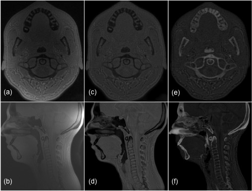
Fig. 1 shows two representative sections of a healthy volunteer. The uncorrected magnitude images (Fig. 1a,b) show proton-density weighted contrast and the signal intensities are increasingly lower towards the center due to the coil sensitivity variation in the axial image (Fig. 1a). The severity of inhomogeneity is apparent in the sagittal image (Fig. 1b). After signal intensity correction, the images in Fig. 1c and Fig. 1d show homogeneous intensities across the FOV. The short T2 tissues such as the teeth and the cervical spine are well depicted in the bright bone images (Fig. 1e,f). The volume-rendered images in Fig. 2 show excellent depiction of the skull and teeth. The C-spine is also well visualized.The artifacts in Fig. 2d and Fig. 2f in the mouth were due to metal dental work.
Due to the configuration of the head coil used, the image signal-to-noise ratio (SNR) in the head was noticeably better than that in the C-spine. Further improvement in C-spine visualization can therefore be achieved by using appropriate coil adapted to the shape of the neck, e.g., flexible array coils.
Conclusion
With optimized high resolution ZTE MR imaging and advanced image processing, high quality cortical bone imaging of the human skull and cervical spine has been demonstrated on a clinical 3T scanner in a reasonable acquisition time (<6 minutes). This can potentially allow use of MRI for C-spine imaging as well as other cortical bone structures.Acknowledgements
No acknowledgement found.References
1. Eley et al., Br J Radiol 2012; 84:272-278. 2. Du et al., NMR Biomed 2013; 26:489-506. 3. Wehrli F. J Magn Reson 2013; 229:35-48. 4. Zhang et al., Med Image Comput Comput Assist Interv 2009; 12: 852–859. 5. Wiesinger et al., Magn Reson Med 2016; 75:107–114.Figures