1417
A Comprehensive Gradient Trajectory Correction Strategy for Clinical 3D UTE Imaging1UIH America, Inc, Houston, TX, United States, 2Shanghai United Imaging Healthcare Co., Ltd, Shanghai, China
Synopsis
A comprehensive gradient trajectory correction strategy for non-selective 3D radial UTE imaging was proposed that consistently produces images free of gradient related artifacts by incorporating the actual gradient waveform, and features user friendliness and time-saving by removing the need for separate calibration scan. Application of this innovative design on phantom and volunteer imaging indicates it is a robust and promising technique.
Introduction
Ultrashort echo-time (UTE) imaging detects short T2 species which otherwise show little or no signal on conventional MRI. Largely due to use of ramp-sampling, 3D radial UTE is notoriously sensitive to gradient trajectory deviation from design resulting from gradient delay, eddy currents, and imperfections in gradient amplifier. Existing trajectory correction techniques 1-5 either presume an over-simplified model in which the gradient waveform is assumed to be perfect other than a delay time awaits determination, or require dedicated separate calibration scans in advance that are often time-consuming and difficult to perform. Furthermore, some of these techniques require re-calibration when gradient waveform changes, making them inept to respond to versatile clinical imaging needs. This study proposes a comprehensive gradient trajectory correction strategy for non-selective 3D radial UTE imaging that: 1) consistently produces images free of gradient related artifacts by incorporating the actual gradient waveform, and 2) features user friendliness and time-saving by removing the need for separate calibration scan.Methods
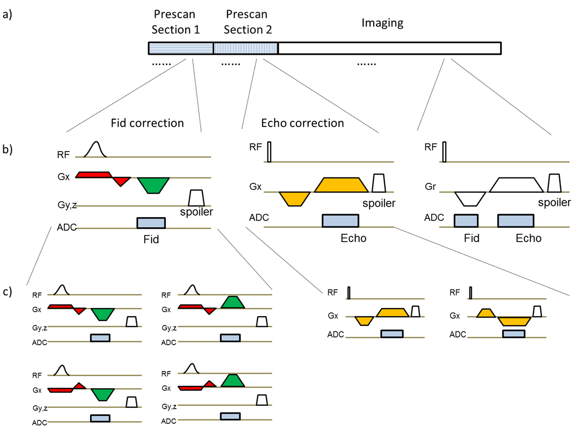
A prototype 3D spoiled gradient-echo sequence was developed to support center-out UTE ramp-sampling (Fid) and echo (Echo) imaging. Fid and Echo gradient corrections were respectively performed during prescan section 1 and 2 (Fig.1). The Fid correction measured the actual gradient waveform using off-center slice-selection excitation followed by readout during ramp-sampling. Specifically, four measurements $$${{S}_{1}},{{S}_{2}},{{S}_{3}}$$$ and $$${{S}_{4}}$$$ were first performed by varying the polarity of the excitation and readout gradients. Next, the actual gradient waveform $$$G(t)$$$ was calculated by taking the phase derivative of readout signals and then by averaging across measurements:
\[G(t)=\frac{\sum\limits_{i=1}^{4}{{{f}_{i}}(t)}}{4*L*\gamma }\]
, where $$${{f}_{i}}(t)=\frac{d\angle {{S}_{i}}(t)}{dt}$$$ is assumed positive and is the phase derivative of the readout signal $$${{S}_{i}}(t)$$$, $$$L$$$ is the off-center distance, and $$$\gamma $$$ is the gyro-magnetic ratio. As discussed previously 6, this approach can cancel out effects from global B0 off-resonance, linear background field and eddy currents from the excitation module, while leaving only the actual waveform of the readout gradient intact. The Echo correction acquired readout signals with opposite gradient polarities and a delay was calculated following procedures similar to those previously published 7. Averages were used to improve measurement accuracy. The above process was repeated for each physical axis.
During reconstruction, the k-space position of each Fid data point was corrected with help from the actual waveform measured, and that of each Echo data point was corrected using the gradient delay measured. Trajectories of spokes off the physical axes were superimposed from that on the axes.
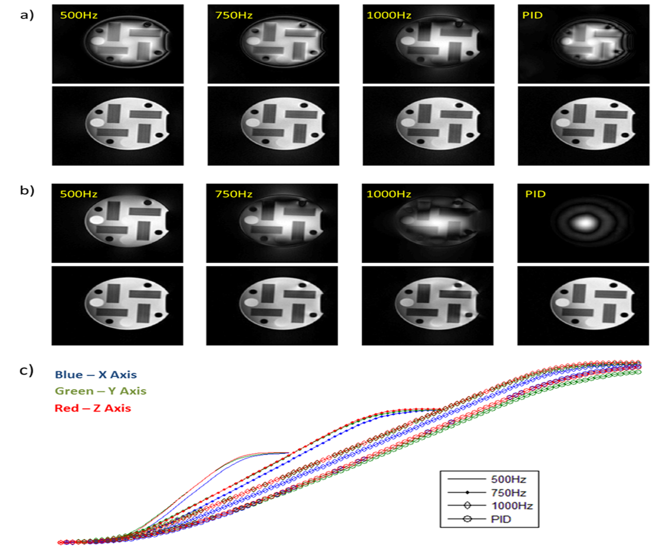
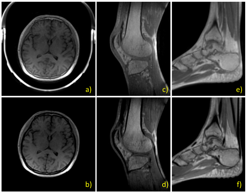
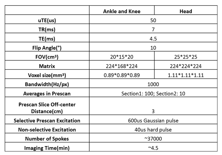
The proposed technique was verified on a phantom and results were compared with images reconstructed without using this strategy. To further evaluate its performance under different gradient waveform shapes, bandwidth was varied from the default 1000Hz to 500 Hz. In one more test the gradient system characteristics were modified by changing the scanner’s proportional–integral–derivative (PID) settings, a set of fundamental parameters that control gradient amplifiers’ response. To demonstrate the proposed technique’s potential in clinical use, a total of six healthy volunteers were recruited after informed consent for imaging of the head, knee, and ankle. Imaging was performed on a 1.5T MR system (uMR 570, United Imaging Healthcare, Shanghai, China). Refer to Table 1 for scan parameters. Phantom data were reconstructed offline while volunteer data were inline reconstructed automatically without human intervene or feedback. Regridding with Kaiser-Bessel kernel and post density compensation was used.
Results
Images acquired and reconstructed with the proposed strategy showed little blurring or ringing artifact associated with uncorrected gradient trajectory, under different bandwidths and with modified system gradient characteristics, while images without correction have obvious artifacts (Fig.2). Typical images of the head, knee, and ankle from healthy volunteers demonstrated consistent good quality across applications (Fig.3), for both Fid and Echo type of reconstruction.Conclusion and Discussion
A comprehensive gradient trajectory correction strategy for non-selective 3D radial UTE imaging was proposed. Phantom results indicated that it is a robust correction technique that performs well under various conditions. Its preliminary use in human imaging was corroborated by healthy volunteer results. This technique does not require dedicated separate calibration scan, is easy to implement, and is time-efficient. The added prescan only costs less than 10 seconds, a minor increase when compared to typical UTE scan times of at least several minutes. In clinical scenarios when it is necessary to frequently change imaging parameters such as FOV, resolution, and bandwidth, this technique is of great potential in accommodating imaging needs for a variety of applications and patient sizes. The proposed technique is expected to aid trajectory correction in other non-Cartesian imaging as well, such as spiral acquisition.Acknowledgements
No acknowledgement found.References
[1] Herrmann KH, Krämer M, Reichenbach JR. Time Efficient 3D Radial UTE Sampling with Fully Automatic Delay Compensation on a Clinical 3T MR Scanner. PLoS One. 2016 Mar 14;11(3):e0150371.
[2] Takizawa M, Hanada H, Oka K, et al. A Robust Ultrashort TE (UTE) Imaging Method with Corrected K-space Trajectory by Using Parametric Multiple Function Model of Gradient Waveform. IEEE Trans Med Imaging. 2013 Feb;32(2):306-16.
[3] Addy NO, Wu HH, Nishimura DG. A Simple Method for MR Gradient System Characterization and k-Space Trajectory Estimation. Magn Reson Med. 2012 Jul; 68(1): 120–129.
[4] Campbell-Washburn AE, Xue H, Lederman RJ, et al. Real-time Distortion Correction of Spiral and Echo Planar Images Using the Gradient System Impulse Response Function. Magn Reson Med 2016 Jun 01;75(6):2278-85.
[5] Liu Q, Gong X, Guan X, et al. An Iterative Gradient Delay Correction Method for 3D UTE Imaging. Proc. Intl. Soc. Mag. Reson. Med. 25 (2017): 4029.
[6] Zhang W. U.S. Patent 6,448,773, 2002.
[7] Block KT, Uecker M. Simple Method for Adaptive Gradient-Delay Compensation in Radial MRI. Proc. Intl. Soc. Mag. Reson. Med. 19 (2011): 2816.
Figures