1384
Uncompromised MRI of knee cartilage while incorporating sensitive sodium MRI1Radiology, University Medical Center Utrecht, Utrecht, Netherlands, 2WaveTronica, Utrecht, Netherlands, 3Biomedical Engineering, Eindhoven University of Technology, Eindhoven, Netherlands, 4Orthopaedics, University Medical Center Utrecht, Utrecht, Netherlands, 5BioImaging Center, Lund University, Lund, Sweden
Synopsis
The goal of this work is to implement a dual tuned sodium-proton coil as transceiver for sodium and transmitter for hydrogen with a high-density proton receive array and compare the proton imaging performance with a state-of-the-art single tuned knee coil. A double-tuned knee coil was constructed as a shielded birdcage and 15 channel proton receiver coil embedded within the double-resonant birdcage. The double-tuned coil was implemented with comparable proton quality and acceleration possibilities compared to the single-tuned alternative while also being able to acquire high SNR sodium images.
INTRODUCTION
Cartilage degeneration is characterized by loss of glycosaminoglycans (GAG) on the surface of the cartilage. This GAG loss can be quantified by using sodium MRI due to its direct relation with GAG content 1,2. Sodium imaging requires double tuned RF coils, but the proton image quality of such coils is often severely compromised. Reasons for this is that the number of proton receive channels are often severely reduced and that double tuning may degrade the intrinsic sensitivity of the RF coil. However, when incorporating an array of single tuned 1H coils inside a volume sodium transceiver, proton imaging performance may remain intact. Therefore the goal of this work is to implement a dual tuned sodium-proton coil as transceiver for sodium and transmitter for hydrogen with a high-density proton receive array and compare the proton imaging performance with a state-of-the-art single tuned knee coil.METHODS
A double-tuned knee coil was constructed as a shielded birdcage (12 rods with a length of 15 cm) and 15 channel proton receiver coil embedded within the double-resonant birdcage. The 1H transmit and receive coils could be actively detuned using standard PIN diode circuitry. The fifteen overlapping proton receive elements were each 5 cm width and 9.5 cm in length and connected to low impedance preamplifiers used for preamplifier decoupling and signal amplification before interfacing to the 7T MRI system (Achieva; Philips Healtcare, Best, Netherlands). To validate the efficiency of the proton coil, our double tuned (DT) coil was compared with a vendor-built single tuned (ST) alternative (28 channel receive; Quality Electrodynamics LLC, Ohio, USA). SNR, g-factor acceleration maps and B1+ measurements were carried out in the DT coil (4 volunteers) and ST coil (8 volunteers) after informed consent was signed. SNR maps were constructed from noise scans, whereas the signal maps were corrected for B1+ performance by normalizing with the B1+ maps. G-factor maps were reconstructed to analyze the acceleration possibilities in both coils.RESULTS
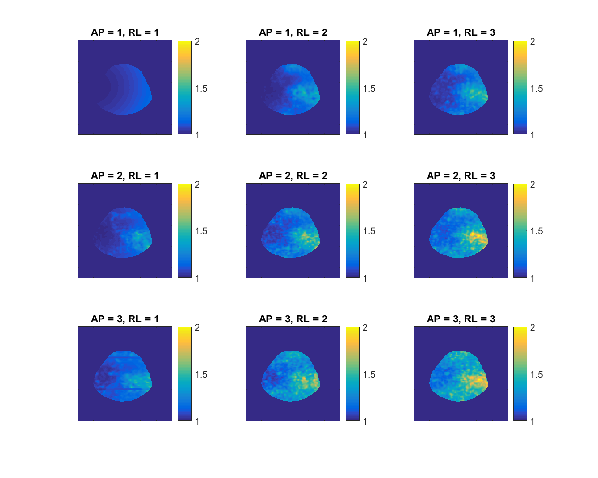
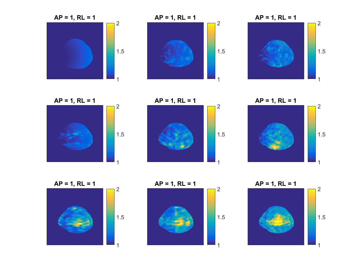
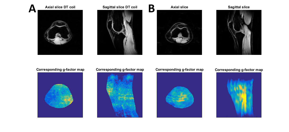
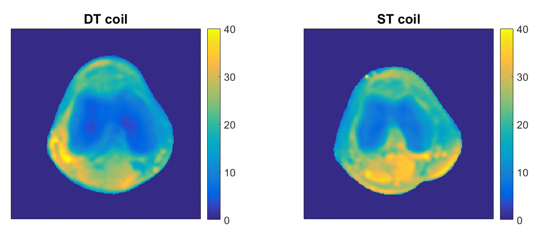
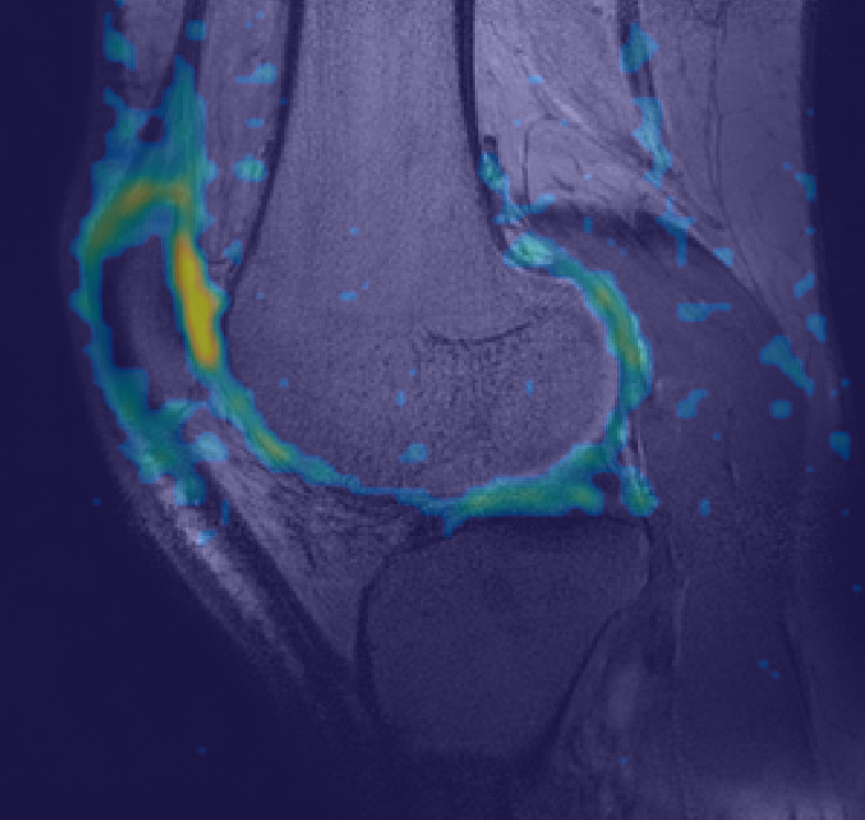
G-factor maps were reconstructed with SENSE acceleration factors of up to three in both directions (AP and RL). Figure 1 shows the axial g-factor maps of our DT coil, which indicated that a SENSE acceleration of 9 was feasible in this coil (AP = 3, RL = 3, maximum g-factor 1.9). Figure 2 shows the same axial g-factor maps, acquired with the ST coil where the g-factor maps had a similar hotspot at SENSE acceleration of 9, with a maximum g-factor of 2.2. Figure 3 shows a typical axial and sagittal slice for each coil with corresponding g-factor maps (with SENSE AP = 3, RL = 3). SNR maps are shown in figure 4 for our DT coil and the ST coil, indicating that both had similar SNR. The SNR maps were corrected for B1+ performance, hence reflecting intrinsic coil sensitivity. Average SNR in the trochlear cartilage was 26.6 in the DT coil (standard deviation = 4.1, N = 4) and 28.3 in the ST coil (standard deviation 1.6, N = 8). Figure 5 shows a sodium scan from the DT coil overlaid on a proton density weighed anatomical scan.DISCUSSION / CONCLUSION
The g-factor maps of the DT coil showed that its having the same acceleration possibilities compared to the ST coil, both coils lost some performance with acceleration factor of 9 (AP = 3, RL=3, g-factor > 2). The patterns within the g-factor maps showed some differences, which could be attributed to the differences in receive array designs. The SNR maps did not show substantial differences, indicating that the proton performance was not hampered by the addition of a sodium receive/transmit coil. This is underlined by figure 5, showing that we achieved high SNR sodium images while maintaining good quality proton scans. The addition of a sodium transmit and receive coil is beneficial because both nuclei can be scanned in the same session, without changing coils. By implementing an interleaved scanning protocol, sodium and proton scans can be acquired at the same time to be even more time efficient 3. In conclusion, a DT coil was implemented with comparable proton quality compared to the state-of-the-art ST alternative while also being able to acquire high SNR sodium images.Acknowledgements
No acknowledgement found.References
1. Madelin G, Jerschow A, Regatte RR. Sodium relaxation times in the knee joint in vivo at 7T. NMR Biomed. 2012;25(4):530-537. doi:10.1002/nbm.1768.
2. Trattnig S, Welsch GH, Juras V, et al. Na-23 MR Imaging at 7 T after Knee Matrix-associated Autologous Chondrocyte Transplantation: Preliminary Results. Radiology. 2010;257(1):175-184. doi:10.1148/radiol.10100279.
3. de Bruin PW, Koken P, Versluis MJ, et al. Time-efficient interleaved human 23Na and 1H data acquisition at 7 T. NMR Biomed. 2015;28(10):1228-1235. doi:10.1002/nbm.3368.
Figures