1194
Imaging at 0.5 T with high-performance system components1Research and Development, Synaptive Medical, Toronto, ON, Canada, 2Physics & Astronomy, University of Western Ontario, London, ON, Canada
Synopsis
While the predominant MR market share is taken up with high-field systems (1.0T and above), there are benefits to imaging at mid-field. Mid-field systems can have a compact fringe field, low weight, compact design facilitating siting, low susceptibility-based geometric distortion and reduced RF heating with or without the presence of implants. Mid-field systems have historically been associated with sub-par image quality due to lower signal-to-noise behavior coupled with an absence of state-of-the-art hardware. Here we present a head-only, superconducting mid-field system designed with high-performance system components aimed at achieving comparable image quality to typical 1.5T systems in comparable scan times.
Introduction
Clinical MR scanners traditionally operate at high field; for example in 2012 89% of MR scanners in the US operated at a field strength of 1.0 T or higher1. Lower main magnetic field strength magnets result in lower polarization which impacts the available signal, but can have important advantages such as smaller-size, lighter-weight, more economic magnets, compact fringe fields, easier siting and installation requirements, reduced SAR, reduced heating around implanted devices, and reduced susceptibility-based image artifact and distortion. Traditionally systems below 1.0 T are either permanent magnet systems, which lack many of the benefits of a superconducting system, or are superconducting systems targeted as low-cost "value" systems with derated system specifications compared to higher-field systems. This can result in degraded image quality compared to higher field systems. In this abstract we propose a mid-field superconducting system which marries the benefits of mid-field imaging with state-of-the-art system components that can achieve clinically relevant head MR imaging in comparable scan times to routine 1.5 T imaging.System Components
The perception of imaging at mid-field is one of degraded image quality resulting from the reduced signal-to-noise (SNR). Here we present a scanner design targeted for head imaging which ameliorates this issue through the implementation of high-performance system components. These include:
High performance gradients. Our implementation of a gradient coil design targeted for head imaging allows for 100 mT/m max gradient strength with a max slew rate of 400 T/m/s simultaneously per axis. This gradient performance can be leveraged to achieve increased SNR by reduced echo times (e.g. in EPI and diffusion scans), and increased readout duty-cycles by reducing gradient rewinder and prewinder times. This is possible given that it has been demonstrated that PNS thresholds are significantly less restrictive for head-only gradient coil geometries2.
High B1+. There is an approximately 9-fold reduction in SAR at 0.5 T compared to 1.5 T and a 36-fold reduction compared to 3.0 T for the same RMS B1+. With this reduction in SAR we are able to implement a transmit system capable of maximum B1 fields greater than 50 uT without exceeding patient heating limits. This B1 can be used to achieve significantly shorter RF pulses to obtain echo trains with shorter duration which are capable of capturing signal with less T2 decay, higher bandwidth RF pulses in shorter times to reduce crushed signal loss due to imperfect slice profiles, and allows for greater readout duty cycles through reduced RF pulse duration.
Digital receive chain. At 0.5 T the Larmor frequency is approx 21 MHz which enables direct sampling of the received signal without the need for mixing the incoming signal to an intermediate frequency. This eliminates additional noise contributions coming from out of band signal and allows for high fidelity digital filtering of the direct signal. In addition, the signal is digitized at the magnet to further reduce noise contributions.
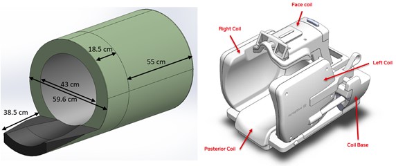
Adjustable multi-channel head-coil. We have implemented a novel, multi-channel head receive coil with movable side and top panels which enables optimal placement of the receive coil elements in a patient-specific manner. This is possible due to careful coil design and reduced coil coupling at 0.5 T.
Methods
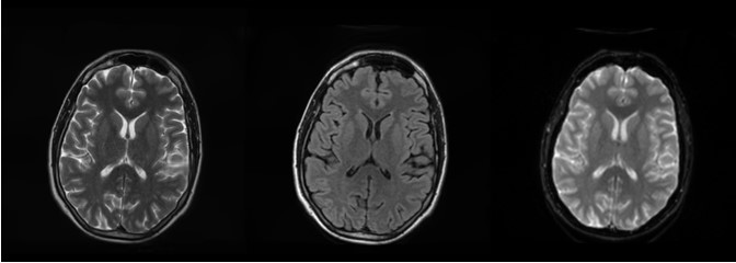
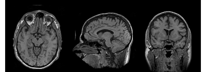
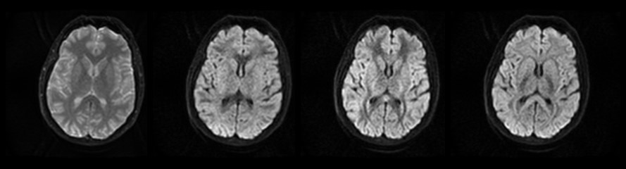
Routine 1.5 T head-imaging protocols were adapted to run on a mid-field system built with the high-performance system components described above. A custom pulse sequence and reconstruction environment was used to drive the system and reconstruct images. Scan protocols were optimized for 0.5 T but within the constraints of maintaining a comparable scan time to the equivalent 1.5 T protocol. Note that image quality and SNR is improved by tailoring scan protocols to the decreased tissue T1s and increased tissue T2s found at 0.5 T compared to higher fields3-5. Based on scan parameter guidance from ACR6, ADNI7 and consulting radiologists we acquired images at the following spatial resolutions: T2 and T2-FLAIR at 1x1x5 mm, T2*-weighted EPI at 2x2x5 mm, 3D T1w at approximately 1.2 mm isotropic resolution, and DWI at 2x2x5 mm.Results
Sample healthy volunteer images using the protocols derived for 0.5 T are provided in Figures 1-3 and demonstrate diagnostic image quality with good tissue contrast.Conclusion
Mid-field MR systems have distinct advantages that can directly impact increased accessibility of MRI. We present evidence that mid-field MR systems need not be associated with mediocre image quality. Engineering a system with high performance components enables diagnostic quality imaging at 0.5 T.
Acknowledgements
We acknowledge the Mitacs Accelerate program for grant funding in support of one of the authors.References
- IMV MR Market Analysis Report, 2012
- Lee SK et al, Magn Res Med, (2016), 76:1939
- Imran J, Langevin F, et al, Magn Reson Imag, (1999), 17:1347.
- Steinhoff S, Zaitsev M, et al, Magn Reson Med (2001), 46:131
- Stanisz G, Odrombina O et al, Magn Reson Med (2005), 54:507
- https://www.acraccreditation.org/modalities/mri
- http://adni.loni.usc.edu/methods/documents/mri-protocols/
Figures