1053
Ultrahigh spatial and temporal resolution fMRI with implanted CMOS-based planar microcoil at 14.1T1High-Field MR Center, Max Planck Institute for Biological Cybernetics, Tübingen, Germany, 2Graduate Training Centre of Neuroscience, IMPRS for Cognitive and Systems Neuroscience, University of Tübingen, Tübingen, Germany, 3Institute of Theory of Electrical Engineering, University of Stuttgart, Stuttgart, Germany, 4Institute of Microelectronics, University of Ulm, Ulm, Germany, 5Department Physiology of Cognitive Processes, Max Planck Institute for Biological Cybernetics, Tübingen, Germany, 6Department for Biomedical Magnetic Resonance, University of Tübingen, Tübingen, Germany
Synopsis
Compared to electrophysiological or optical recording of brain activity, fMRI has a rather low spatial and temporal resolution. Here, we propose the use of implanted microcoils for studying animal brain activity in-vivo with ultra high sensitivity compared to conventional coils. A fully integrated CMOS NMR transceiver containing an on-chip-microcoil, integrated amplifiers and a demodulator is used to acquire ultra-localized signal (10nl) at ultrahigh temporal resolution (5ms) showing unprecedented high speeds and spatial resolutions of the BOLD response.
INTRODUCTION
Reducing the size of MR coils improves the sensitivity and reduces the volume from which signal is acquired. Therefore, to obtain high sensitivity data from small, well-localized volumes at high temporal resolution, we implanted a miniaturized coil into the brains of healthy rats. A fully-integrated CMOS1 NMR transceiver containing an on-chip microcoil, an integrated RF-amplifier, preamplifiers and signal conditioning electronics was designed, which reduces noise, signal loss and possible coupling to other sources and avoids signal contributions from feeding wires2,3. This system samples the MR signal within a very confined spatial region (~10nl) at a temporal resolution of microseconds, without the use of gradients for spatial encoding. Similar to the one-coil-one-voxel (OVOC) principle, this local sensor samples the free induction decay or steady state induction signal at a rate that is comparable to electrophysiological or optical methods.METHODS
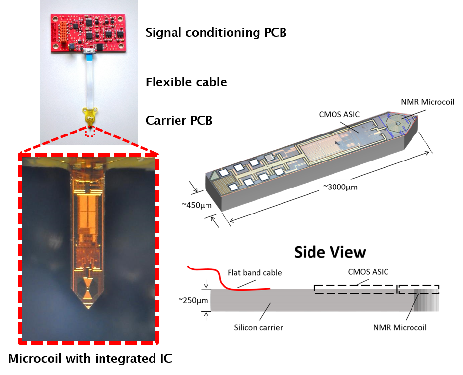
The fully-integrated NMR transceiver includes an on-chip broadband MR-microcoil (300µm-diameter double-spiral coil)2,3 on a silicon substrate with a width of 450µm, a length of 3000µm, and a triangular tip for easier insertion into the brain tissue, with a sensitive volume around 10nl. This NMR transceiver chip is directly bonded to a small supporting PCB (Fig1). A 3cm long flexible cable connects the probe head to a signal-conditioning PCB for amplification. The processed signal is then sent to a National-Instruments acquisition card (NI PXIe-6368, National Instruments, Austin, TX, USA) outside the scanner room for A/D conversion and digital signal processing, similar to Ref. 1-4. The microcoil is then used as transceiver (TX/RX)1,2.
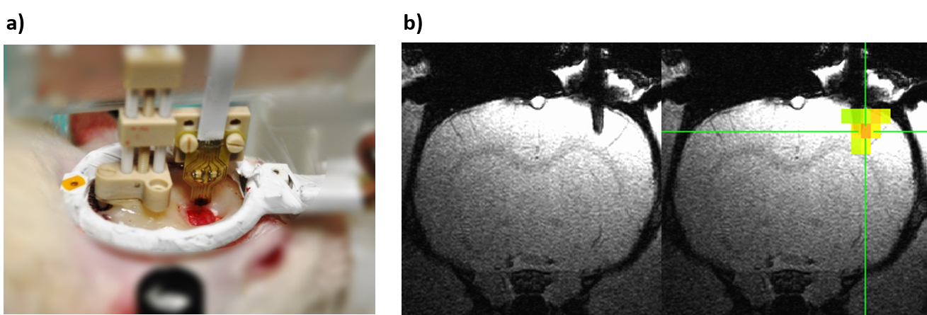
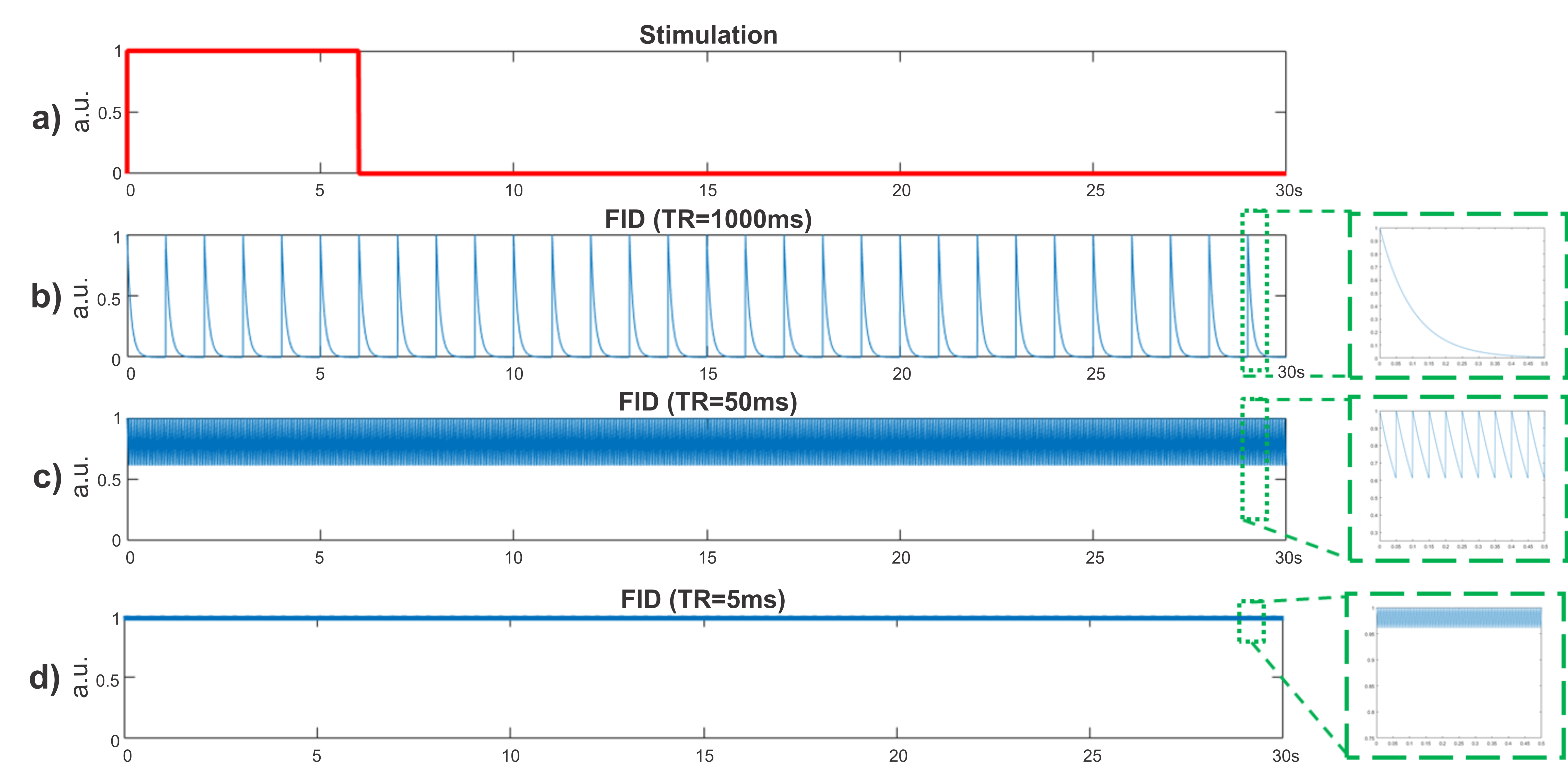
Healthy, anaesthetized rats (Sprague-Dawley, male, 402±49grams) were examined with the implanted microcoil in combination with a conventional surface coil for functional MR experiments in a 14.1-T/26-cm horizontal magnet (Magnex Scientific, Abingdon, Oxfordshire, UK) small-animal scanner. The study was approved by the local authorities and was in full compliance with the guidelines of the European Community for the care and use of laboratory animals. A craniotomy was performed for targeting the somatosensory cortex (S1), 3.5mm of the midline and 0.5mm posterior to the bregma5 in order to implant the microcoil. The microcoil was attached to a holder, which was fixed to the skull with bone cement. The microcoil was then slowly inserted 1.5mm to 2mm into the brain. The rat was moved to a MR-compatible bed and placed inside the scanner (Fig2). The microcoil is used to acquire FIDs with a pulse-acquire sequence without using gradients during electrical forepaw stimulation and at rest ([6s,24s]x20), with 10µs excitation pulses applied with the microcoil to optimize the signal amplitude. Repetition times - TR of 5ms, 50ms and 1000ms were used, corresponding to 120000, 12000 and 600 FIDs per experiment, respectively (Fig3). The complex quadrature time-domain signals were sampled at 2MS/s and 16-bit resolution, saved as raw data and evaluated after the experiment. For these measurements, the shim was carefully adjusted manually, requiring a strong compensation in the X direction (10kHz/cm) for getting a water-peak linewidth of ~30Hz. Additionally, EPI measurements during rest and forepaw stimulation were also carried out in a separate experiment with a conventional 20x30mm surface-coil, using a gradient-echo EPI sequence (matrix size: 64×48, FOV=43×38mm2, eight 1mm slices, TR/TE=1000ms/9ms, bandwidth=300kHz) and similar stimulation paradigm as the microcoil experiment.
RESULTS
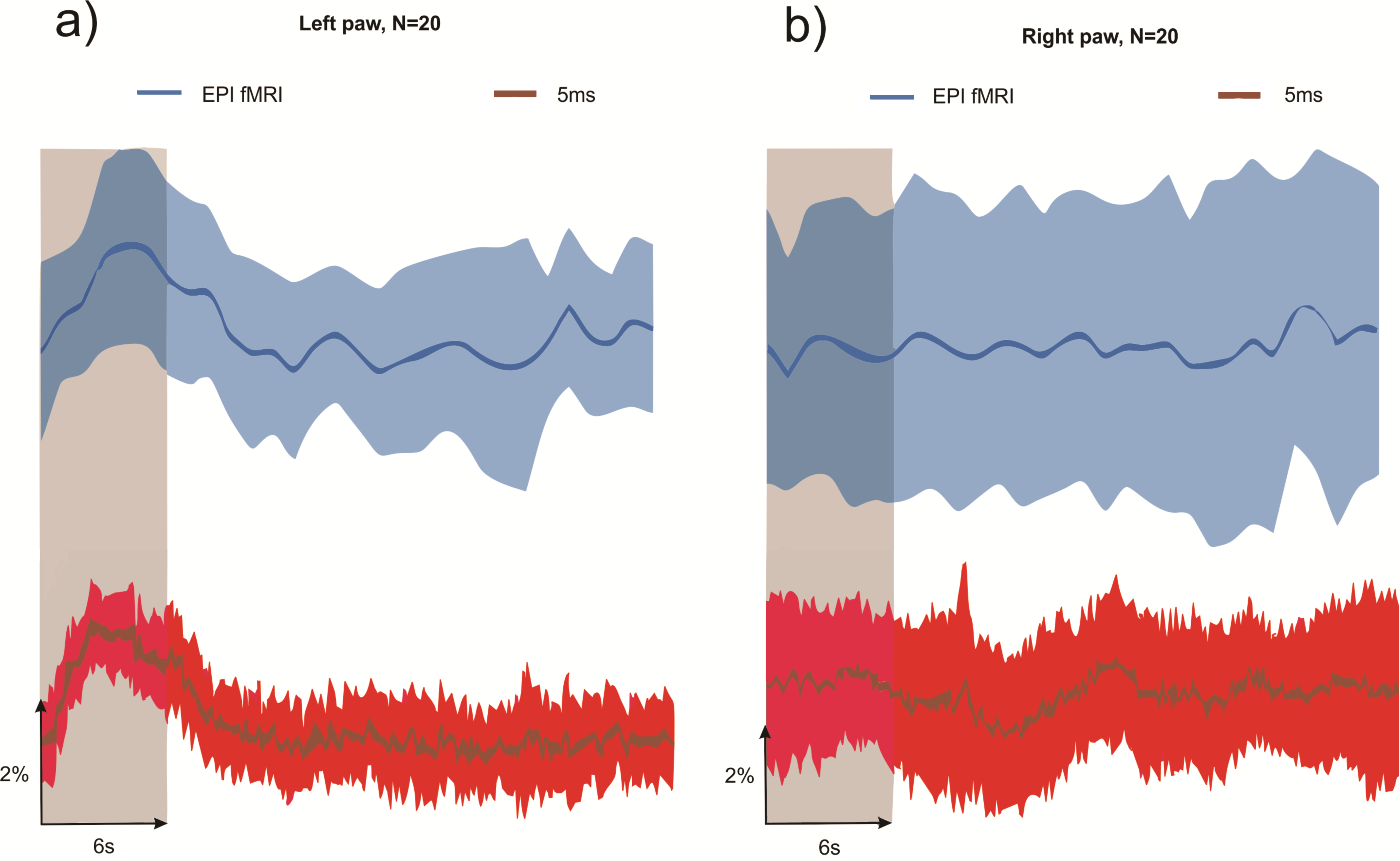
Figure 4 shows a comparison of BOLD responses acquired with the conventional surface coil and the microcoil at 1000ms and 5ms temporal resolution, respectively. The microcoil response is obtained by averaging over all stimulation epochs, extracting the area under the magnitude of the resulting FIDs, yielding a single value per FID with temporal resolutions up to 200Hz (for TR=5ms). Additionally, the functional signals were low-pass filtered with a 3Hz Gaussian filter to reduce the noise, since no visible stimulation-related features beyond that frequency were observed. Signal changes of around 2% were observed during forepaw stimulation as depicted in Fig4. The contralateral responses for a stimulation of the right-paw (Fig4b) showed no response in any measurement, indicating that the signals are indeed the hemodynamic response to the stimulation of the left-paw.CONCLUSION
Exceptional spatial and temporal resolution was possible with the microcoil, detecting BOLD and flow-related signal changes during electrical stimulation within 10nl of volume and 5ms of temporal resolution. This new technology offers the potential to detect novel effects or MR-fingerprints of neuronal activation. Future work will include the combination of this miniaturized technology with other local and fast methods for neuronal recording such electrophysiology and calcium recording, in-vivo fMRS6, as well as direct quantification for inflow and T2* changes.Acknowledgements
No acknowledgement found.References
-
Handwerker
J. et al. An array of fully-integrated quadrature TX/RX NMR field probes for
MRI trajectory mapping. ESSCIRC.2016:217-220.
- Handwerker
J. et al.Towards CMOS-based in-vivo NMR spectroscopy and microscopy. ISCAS.2017.
- Pérez
Rodas M, et al. 10µm isotropic voxels acquired with a CMOS-based planar
microcoil at 14.1T: Preliminary results, Joint Annual Meeting ISMRM-ESMRMB
2018, Paris, France. 1727.
- Anders
J. et al. A low-power high-sensitivity single-chip receiver for NMR microscopy.
JMR.2016;266:41-50.
- Cox,
R. W. AFNI: Software for Analysis and Visualization of Functional Magnetic
Resonance Neuroimages. Computers and Biomedical Research 29. 1996. 162-173.
- Rodas,
P. et al. Towards fast and highly localized spectroscopy using miniaturized
coils in a 14.1 T animal scanner. In 24th Annual Meeting and Exhibition of the
International Society for Magnetic Resonance in Medicine ISMRM.2016. Singapore.
2402.
Figures