1039
Peripheral Nerve Stimulation (PNS) constrained gradient coil design within a Boundary Element Method Stream Function (BEM-SF) optimization1Computer Assisted Clinical Medicine, Heidelberg University, Mannheim, Germany, 2A.A. Martinos Center for Biomedical Imaging, Charlestown, MA, United States, 3Harvard Medical School, Boston, MA, United States, 4Harvard-MIT Division of Health Sciences Technology, Cambridge, MA, United States
Synopsis
Gradient system performance is increasingly constrained by Peripheral Nerve Stimulation (PNS). Nonetheless, gradient coil windings are optimized using the boundary element stream function method (BEM-SF) incorporating only non-biological metrics. We introduce direct incorporation of PNS constraints into a BEM-SF optimization in addition to the usual constraints. We pre-compute a novel PNS “oracle” matrix of each nerve segment’s likelihood to be excited by a given stream-function basis. The constraint is linear in current, so stimulation likelihood is a simple sum over all stream function bases. This allows convex optimization with a PNS constraint and examination of tradeoffs with linearity, inductance, torque and efficiency.
Target Audience:
MR gradient designers, those interested in MR safetyPurpose:
Spatial encoding in MRI using gradient coils is becoming increasingly limited by peripheral nerve stimulation (PNS). Despite its impact, PNS is currently not directly included in the gradient coil design process. Gradient coil winding patterns are typically designed using the Boundary Element Method Stream Function (BEM-SF) approach under important performance and engineering constraints such as efficiency, linearity, inductance, shielding, and torque [1,2,3]. However, important biological constraints such as PNS are included only indirectly, usually through control of linearity (FOV) [4]. In this work, we present a strategy to directly incorporate PNS constraints in the BEM-SF design/optimization approach in addition to the traditional engineering constraints. Our approach is based on our recent work on modeling magneto-stimulation effects in realistic body models [5,6] and a PNS “oracle”. The resulting convex BEM-SF optimization scheme allows us to generate PNS-optimal designs for multi-layer whole-body and head gradient coils as well as probe the tradeoffs between PNS, torque, inductance, and gradient linearity using L-curves.Methods:
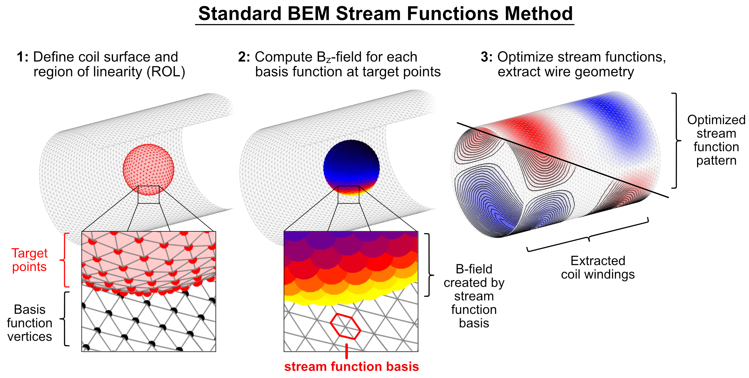
The BEM-SF method provides a gradient wire pattern with optimal $$$B_z$$$ field in the region-of-linearity (ROL) subject to constraints on efficiency (mT/m per Ampere), current density, torque, and inductance. The coil former is represented by a surface mesh on one or more cylinders [4]. For each vertex, a stream function basis (SF-basis) is defined (Fig. 1). These describe a current circulating around that vertex (similar to a small current loop). The vector of stream function basis weights, $$$x$$$, describes the current density pattern from which the $$$B_z$$$ values, current density, and torque are computed as linear expressions via $$$\textbf{C}x$$$, $$$\textbf{D}x$$$, and $$$\textbf{T}x$$$. The inductance is expressed as a quadratic form: $$$x^T \textbf{L} x$$$ . Thus, the problem can be formulated as a quadratic optimization of the inductance subject to constraints:
$$ x_{\text{opt}} = \text{argmin}_x \{ x^T \textbf{L} x \} \text{ subject to } |\textbf{C}x - b_\text{tar}| \leq \epsilon \text{ , } |\textbf{D}x | \leq D_{\text{max}} \text{ , } |\textbf{T}x | \leq T_{\text{max}} \text{ .}$$
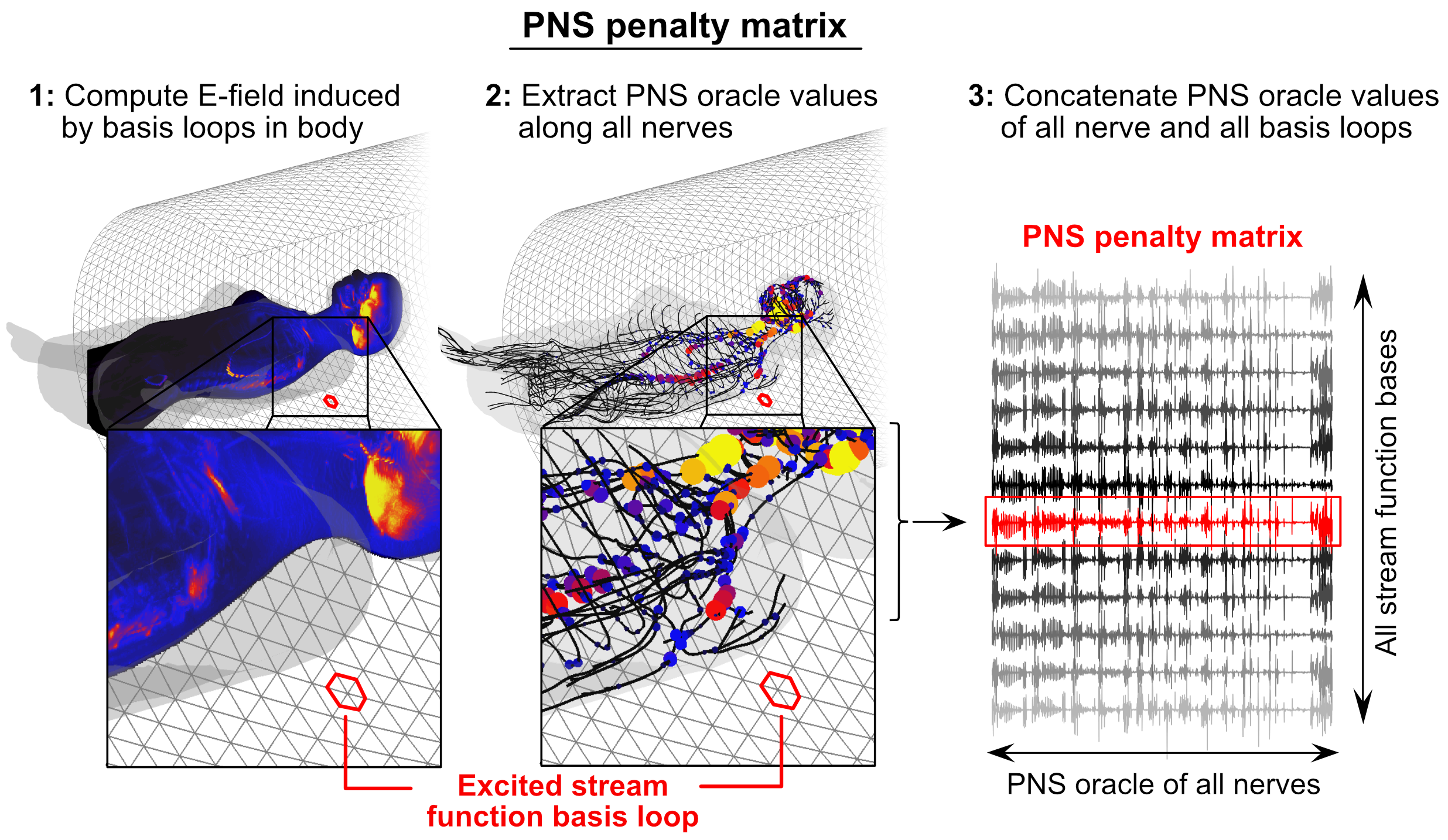
In this work, we incorporate an explicit PNS constraint in the BEM-SF coil optimization. To do so, we additionally compute the E-field induced by each SF-basis in a realistic body model and project them onto a nerve atlas. We pre-compute the PNS oracle (described in a separate abstract [7]) for each SF-basis and nerve segment (Fig. 2). The PNS oracle is a modified version of the neural activation function [8] which provides a linear relationship between a SF-basis’s weight and the likelihood for a given nerve segment to be stimulated. We use a full neurodynamic model [9,10] to show that it correlates well with the inverse PNS threshold ($$$R^2$$$ > 0.99). We arrange the precomputed PNS oracles into a $$$p\times n$$$ stimulation matrix $$$\textbf{S}$$$ ($$$p$$$: number of nerve locations, $$$n$$$: number of stream functions). The PNS effect for each nerve segment is the weighted sum over bases expressed in the vector $$$\textbf{S}x$$$ where $$$x$$$ is the SF weights. Thus, the linear nature of the oracle enables fast interrogation of PNS. The maximum of this vector occurs at the worst-case nerve and is the inverse of the expected PNS threshold for the BEM-SF pattern. Thus, PNS can be constrained in the BEM-SF optimization via the additional constraint: $$|\textbf{S}x|\leq S_{\text{max}}$$
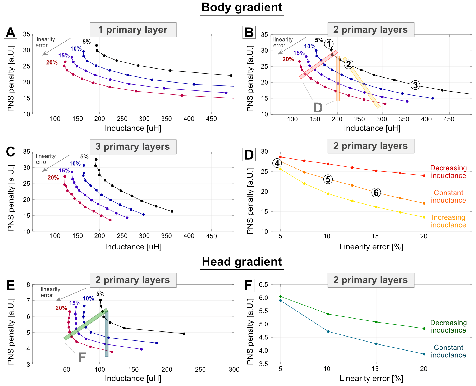
Validation: We tested the ability of our PNS-constrained BEM-SF method to tradeoff PNS against inductance and linearity with constrained torque, current density, and efficiency in a series of body and head gradient winding patterns with 1, 2 or 3 primary layers. In this preliminary study, we did not enforce active shielding. The PNS oracle was evaluated using the female body model (head at isocenter). The design explored 70 cm (body gradient) and 44 cm (head gradient) inner diameter cylinders. To decrease computation time, we obtained the PNS oracle values for only 10% of the stream function bases and used linear interpolation to determine the remaining bases.
Results:
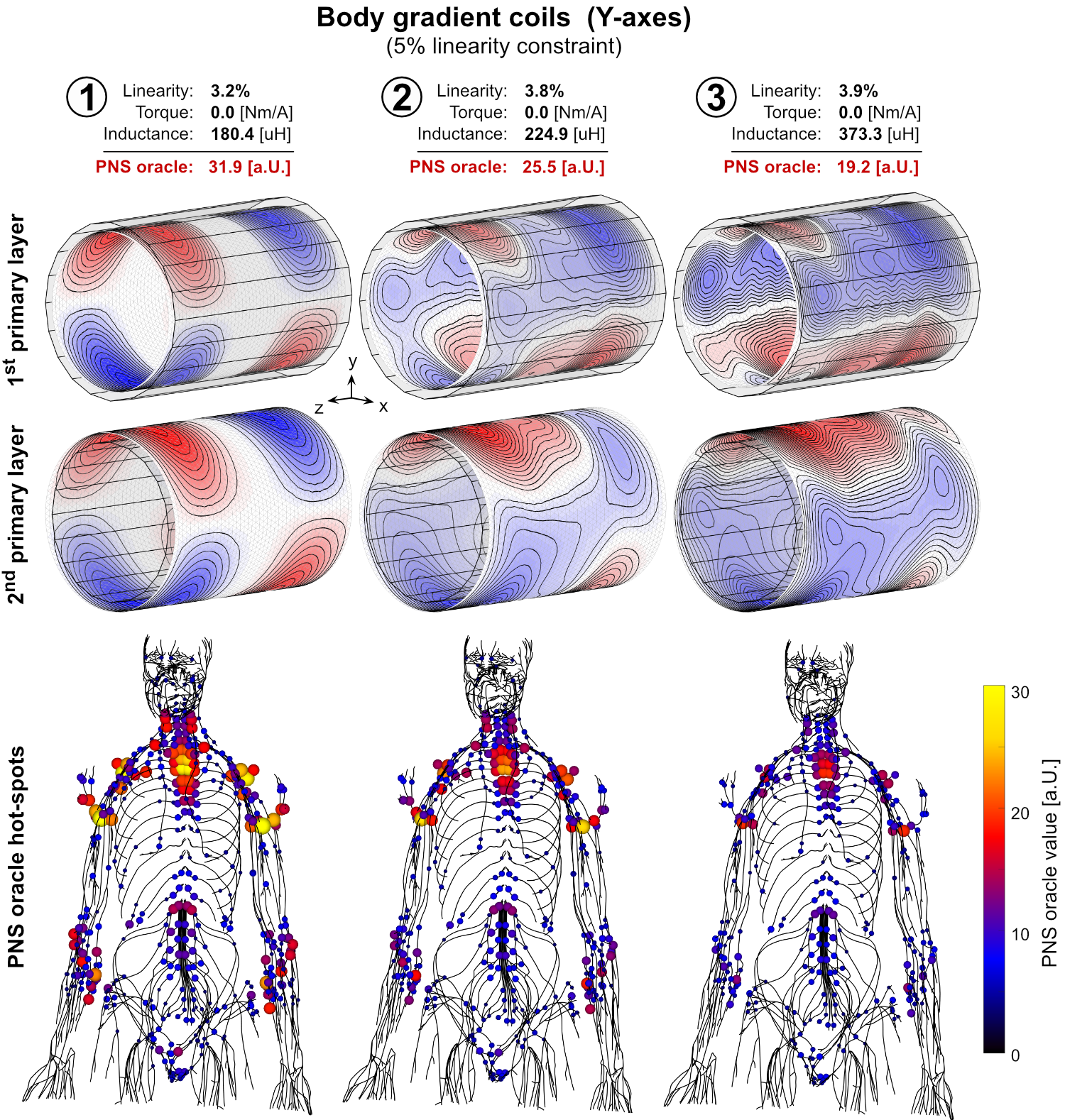
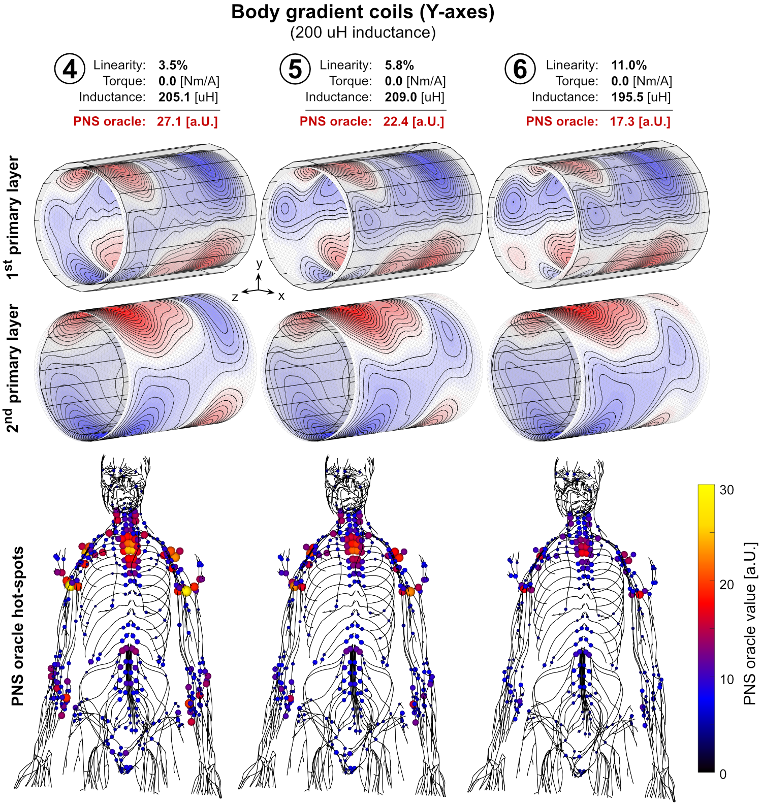
Figure 3, shows the L-curves (“PNS vs. inductance” or “PNS vs. linearity error”) with different numbers of primary layers. With increased inductance, PNS can be reduced significantly without losing linearity. The inductance penalty reduces as layers are added or linearity is sacrificed. Figures 4 and 5 show exemplary coil layouts for the design points noted on the L-curves as well the anatomical locations of prominent oracle values. Enforcing PNS reduction yields significantly different wire patterns with up to 50% reduced interaction with the peripheral nervous system.Conclusion:
We presented an approach to explicitly constrain PNS during the BEM-SF optimization of gradient coils. Introduction of PNS penalties allows the optimization to exploit degrees-of-freedom in coil design (such as concomitant field terms) to reduce PNS or trade it against traditional engineering metrics.Acknowledgements
No acknowledgement found.References
[1] Peeren et al., “Stream function approach for determining optimal surface currents”. Journal of Computational Physics, 191(1), 2003
[2] Lemdiasov et al., “A stream function method for gradient coil design”, Concepts Magn. Reson., 26(1), 2005
[3] Poole et al., “Convex optimisation of gradient and shim coil winding patterns”. Journal of Magnetic Resonance, 2014.
[4] Zhang et al., “Peripheral nerve stimulation properties of head and body gradient coils of various sizes”. Magn. Reson. Med., 39(6), 2003
[5] Davids et al., “Predicting magnetostimulation thresholds in the peripheral nervous system using realistic body models”, Sci. Rep. 7:5316, 2017
[6] Davids et al., “Prediction of peripheral nerve stimulation thresholds of MRI gradient coils using coupled electromagnetic and neurodynamic simulations”. Magn. Reson. Med., 2018
[7] Davids et al., “The PNS oracle: a modified activation function metric for rapid assessment of Peripheral Nerve Stimulation (PNS)”. Proceedings of the 27th Annual Meeting of ISMRM, Montreal, Canada, 2019
[8] Basser et al., “The activating function for magnetic stimulation derived from a three-dimensional volume conductor model”. Medical and Biological Engineering and Computing. 39(11), 1992
[9] McIntyre et al., “Modeling the excitability of mammalian nerve fibers: Influence of afterpotentials on the recovery cycle”. J Neurophysiol. 87(2), 2002
[10] Richardson et al., “Modelling the effects of electric fields on nerve fibres: Influence of the myelin sheath”. IEEE Trans. Bio. Eng. 38(4), 2000
Figures