1037
Improvement of the Transmit Efficiency Using a Miniaturized Artificial Magnetic Conductor Surface for RF shield at 9.4T1ITEE, The University of Queensland, Brisbane, Australia
Synopsis
A novel structure for size-reduction of artificial magnetic conductor surface was designed for 9.4T MRI, aiming to improve the transmit efficiency of RF coils. This design achieved great miniaturization of the EBG unit cell size, which has been reduced to 4.48% of free-space wavelength. The reflection phase coefficient and the dispersion diagram are employed to characterize the EBG structure performance. Compared with a conventional metallic RF shielding plate, full-wave simulation results suggest that the proposed structure can achieve improved transmit efficiency.
Introduction
In MRI system, the radiofrequency (RF) shield is typically used with RF coils to avoid coupling with gradient coils1. However, conventional metallic RF shields suffer from the anti-phase reflection currents, which generate destructive power radiation and interfere with the radiation of RF coils1. This problem can be solved by using an artificial magnetic conductor (AMC) surface, which not only exhibits excellent shielding ability against the electromagnetic (EM) field but also generates in-phase reflection currents2. In recent years, one class of metamaterial, the electromagnetic bandgap (EBG) structure has demonstrated good potential in designing AMC surfaces. However, since the RF coils are preferably placed close to the shield to have a compact structure, miniaturization of the AMC unit cell is of great importance for a better approximation of the homogenous properties of the plane. In this work, an ultra-small structure of the EBG unit cell with lattice dimension of 4.48% of free-space wavelength, is designed for a 9.4 T pre-clinical MRI system. The proposed structure was characterized by the reflection phase and stop-band properties. In addition, full wave simulations were conducted to validate the improvement of transmit efficiency of a surface loop coil by using the designed AMC shielding plane.Method
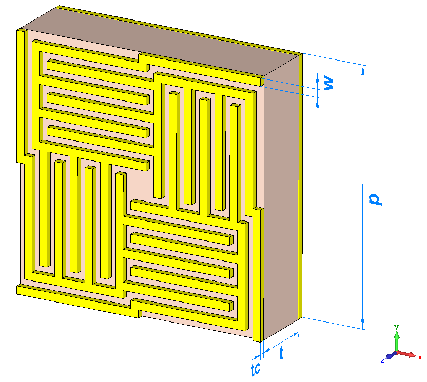
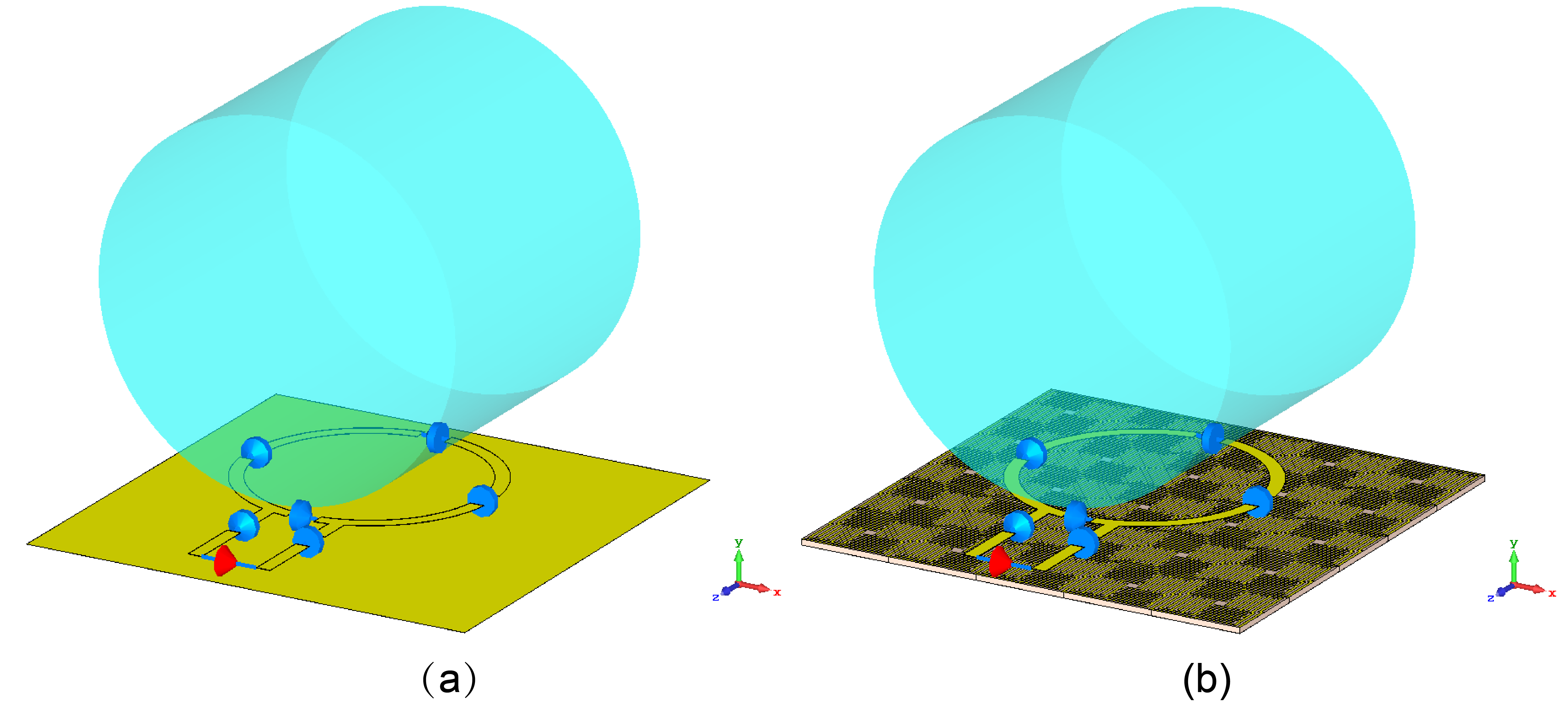
The proposed EBG structure shown in Fig.1 consists of a uniformly distributed periodic metallic pattern printed on the commercially available Rogers 5880 substrate3. For a symmetric EBG surface illuminated by plane waves, the structure can be analytically modeled as a parallel LC resonant circuit with a resonance frequency $$$\omega_{0}$$$ and a surface impedance L give by4: $$$\omega_0=\frac{1}{\sqrt{LC}}$$$, $$$Z=\frac{j\omega{L}}{1-\omega^{2}LC}$$$. The values of the capacitance C and the inductance L are described in4. As shown in Fig.1, this design is based on a 90° rotationally symmetric unit cell geometry, which contains interwoven arms that extend into the neighboring unit cells to increase the total capacitance. This design not only brings down the resonance frequency but also improves the AMC bandwidth. Moreover, a more compact EBG structure can be achieved due to the increased total capacitance. The number of arms and the geometry parameters of the EBG structure were optimized to tune the stop-band to cover the Larmor frequency at 9.4T (400MHz) and minimize the lattice dimension. To demonstrate the enhancement for the RF coil’s transmit efficiency by using the AMC shielding plate, full-wave simulations were conducted with the finite-difference time domain (FDTD) method using CST Microwave Studio (Darmstadt, Germany). The AMC shield was compared with a conventional copper shield when placed underneath a surface loop coil and a phantom filled with brain-equivalent material ($$$ε_{r}$$$ = 58.1 and $$$\sigma$$$ = 0.54 S/m), as shown in Fig.2.Results
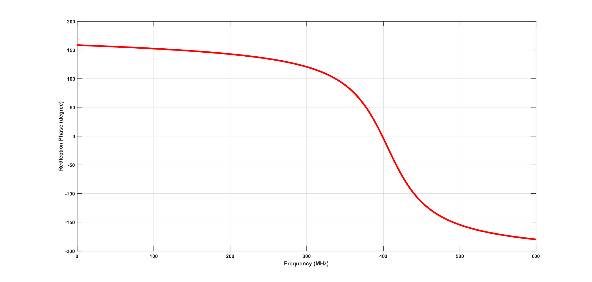
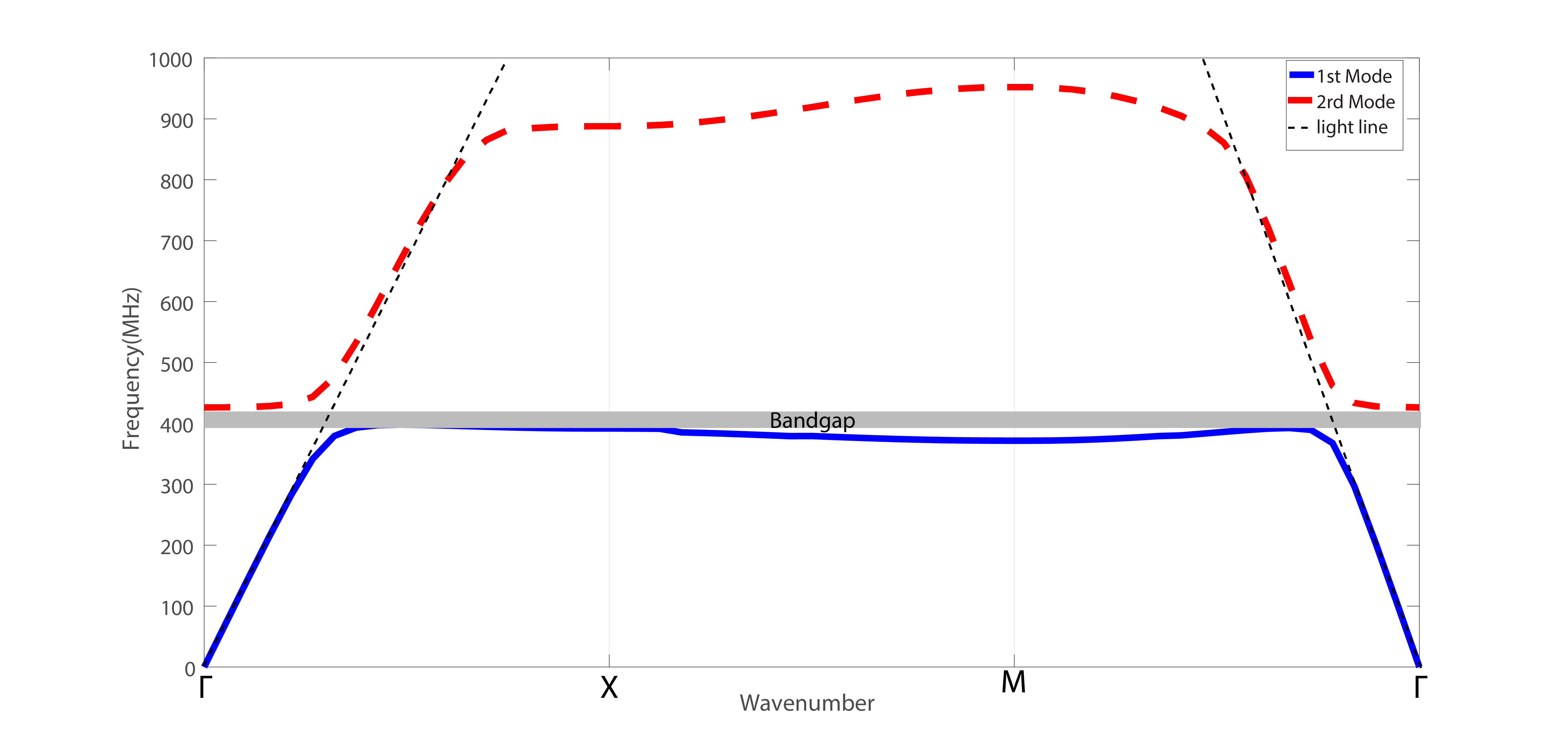
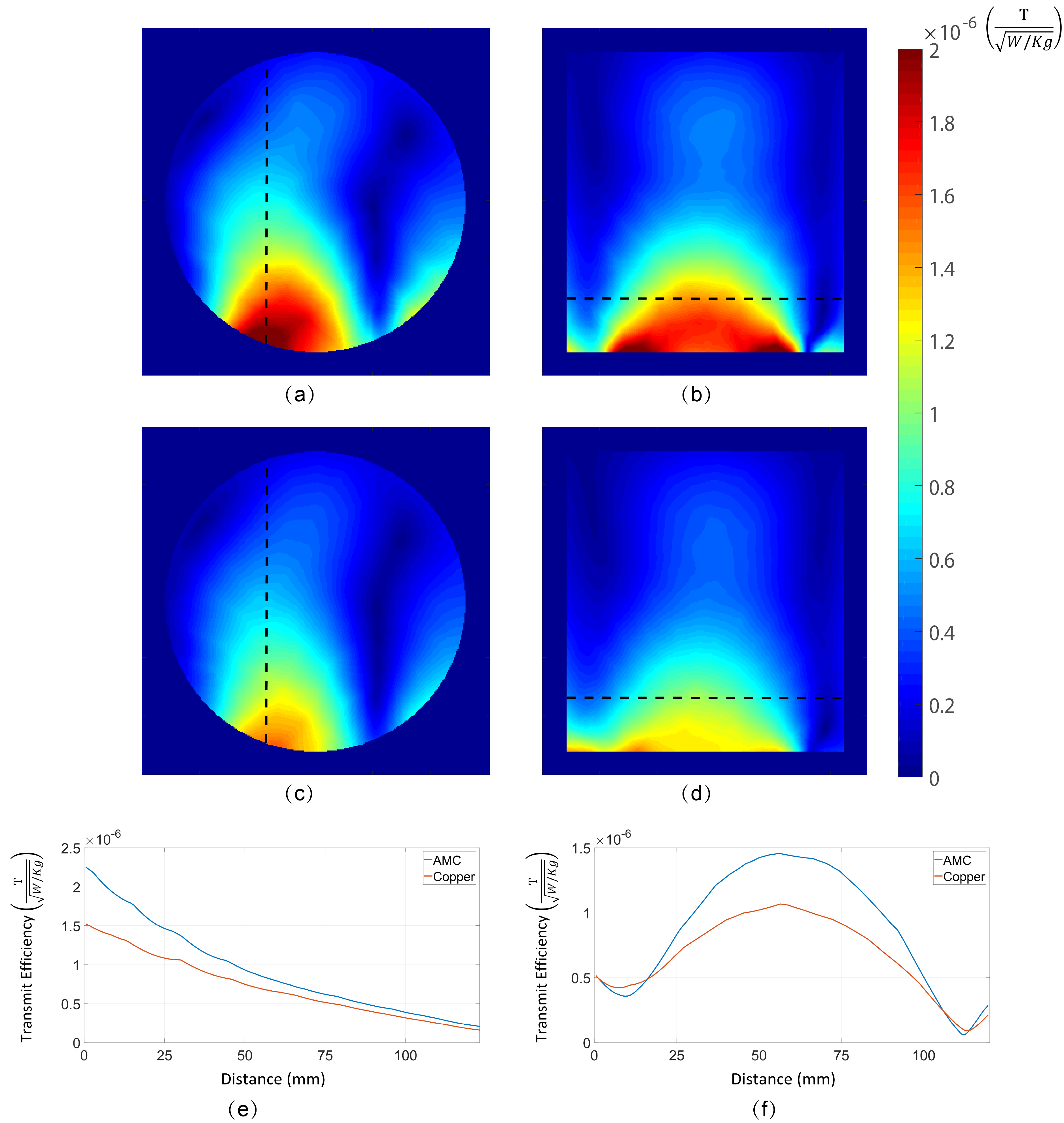
EBG structures are commonly characterized by the reflection phase and the dispersion diagram for incident waves, which describe the working frequency and wave suppression bandgap of the structure, respectively. For the proposed structure, the reflection phase curve is plotted in Fig.3 and the dispersion diagram is given in Fig.4, which clearly demonstrate that the working frequency of 9.4T MRI system is covered by the stop-band of the proposed EBG structure. For the full-wave simulations with phantom, the RF coil’s transmit efficiency is normalized by the maximum SAR as: $$$ B^{eff}_{1}=\frac{|B_1 |}{\sqrt{Max(SAR)}}$$$. A comparison between the transmit efficiency of the RF loop coil using the AMC shield and copper shield is shown in Fig.5 (a)-(d). To quantitatively analyse the improvement of transmit efficiency, the variations of $$$B^{eff}_{1}$$$ along the black dotted lines are shown in Fig.5 (e) and (f). In transverse plane and sagittal plane, improvement up to 47.8% and 36.8% were achieved, respectively.Discussion
The plot of reflection phase and dispersion diagram indicates that the interwoven arms of the periodic metallic pattern can effectively achieve the miniaturization of EBG structure while at the same time keep the band-gap covering the aim frequency (400MHz). Near this frequency, the plane waves are reflected in-phase(90° to -90°) instead of anti-phase as on a copper shield and thereby improving the transmit efficiency. It is validated by full-wave simulation (Fig.5), which presents that the proposed AMC shield greatly improves the transmit efficiency compared with the copper shield.Conclusion
In this work, a novel structure of AMC surface for the 9.4T MRI system is proposed. Miniaturization of the EBG unit cell is achieved using interwoven pattern.Full-wave simulation states that the proposed structure can be used as a shielding plate for the RF coils to improve the transmit efficiency up to 47.8%. In the future, the AMC shield will be prototyped and tested on the 9.4T pre-clinical MRI scanner.Acknowledgements
No acknowledgement found.References
1. Roemer PB, Edelstein WA. RF shield for RF coil contained within gradient coils of NMR imaging device. U.S. Patent No. 4,871,969. 3 Oct. 1989.
2. Yang F, Rahmat-Samii Y. Reflection Phase Characterizations of the EBG Ground Plane for Low Profile Wire Antenna Applications. IEEE Trans Antennas Propag. 51(10 I):2691-2703. doi:10.1109/TAP.2003.817559
3. Rogers Corporation. Advanced circuit materials division high frequency laminates and flexible circuit materials datasheet. Rogers Corporation, Rogers, CT, 2011
4. Daniel S, High-impedance electromagnetic surfaces, PhD dissertation, Dept. Elect. Eng. Univ. California at Los Angeles, Los Angeles, CA, 1999.
Figures