0975
Cervical-Cancer Imaging for brachytherapy planning employing an endo-vaginal array that includes an enhanced forward-looking coil1School of Medicine, Johns Hopkins University, Baltimore, MD, United States
Synopsis
Advanced cervical-cancer spreads from the cervix to the posterior-endometrium and vaginal walls. Improving imaging SNR in this region shortens scan-times required for precisely localizing live-tumor locations before high-dose-rate (HDR) interstitial radiation-therapy. Current endo-vaginal coils focus on vaginal-wall imaging and are in-effective for posterior-endometrium/cervix imaging. This study designs and builds an endo-vaginal array which contains sideways-looking vaginal-wall, and forward-looking cervix/posterior-endometrium elements. The forward-looking “spiral”-coil is metallic-backed, pushing the RF-lobe upwards, enlarging its FOV. The array was designed with electromagnetic simulation and tested in phantoms and swine. Forward-looking SNR over a 3x3x3 cm3 FOV was ~4-8 times that of the spine-array.
Introduction
Advanced cervical cancer consists of relatively large tumors that spread from the cervix into the endometrium and vaginal wall. It is treated in ~40% of cases with radiation therapy, consisting of external beam radiation (EBRT) followed by high dose rate (HDR) interstitial radiation (brachytherapy). MR imaging is performed before brachytherapy to locate remnant tumors that survived EBRT. The goal is to deliver large focused radiation only to living tumor, and minimize radiation to surrounding tissues, which can cause severe side effects. Localizing surviving tumors post-EBRT is difficult, due to post-radiation reduced vascularity, hemorrhage and fibrosis. As a result, extensive MR imaging (T2, DWI, DCE, BOLD) is performed,1 to improve localization of the remnant tumor(s). This leads to long imaging times, since these tissues are positioned midway between the anterior body-array and the posterior spine-array, which reduces surface-coil Signal-to-Noise ratio (SNR). Placing a coil in the vaginal canal is attractive, since during brachytherapy, an obturator is inserted into the vagina to direct the trajectory of interstitial-catheters that are inserted into the tumors for radiation delivery.
Existing endo-vaginal MRI coils are diagnostic coils intended for imaging the vaginal wall or cervix,2,3 and do not meet the above requirements, primarily because their lobe patterns don’t project upwards (in the Superior-Inferior direction) and illuminate the posterior-endometrium. “Flashlight” (forward-looking) lobe patterns that provide strong SNR at distances of 30-40 mm are difficult to deliver within the constraints of the <25 mm diameter vaginal-canal.4
We designed a new imaging array, which includes elements for both sideways (vaginal-wall) and forward-looking (cervix/posterior-endometrium) imaging. The coil is designed to be an “active obturator”, fulfilling the dual roles of supporting HDR-brachytherapy intervention and providing >4 times the SNR of the surface arrays.
Methods
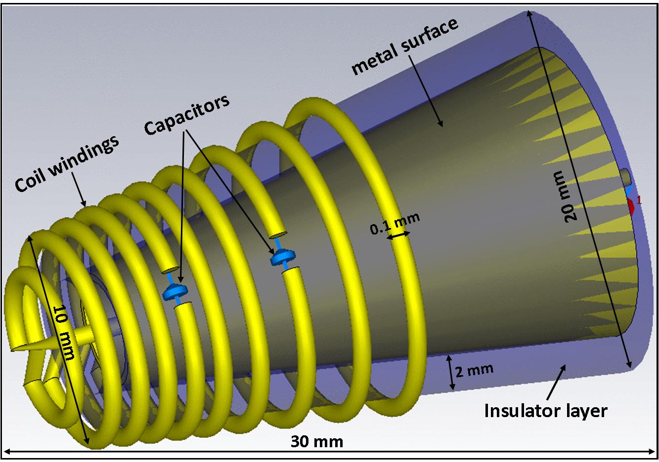
The “pencil” shaped endo-vaginal array has a cone at its top, for the forward-looking coil, and a cylindrical shaft, for the sideways-looking array. Its inner open lumen supports its obturator role. The forward-looking coil was designed utilizing the image-magnetic-field concept, wherein properly-positioned metallic surfaces force magnetic fields to project along selected directions. Design specifics were simulated and tested, since closely-placed metals can reduce the coil quality-factor (Q). Finite-element electromagnetic simulations of the forward-looking coil (CST, Germany) evaluated the effect of the metallic surface on the magnetic-field surrounding the coil. We simulated the metallic surface shape, the distance between the metal and the solenoidal coil windings, and the winding diameter and spacing. Optimal designs were then constructed and tested.
Forward-looking coil design: Two concentric cone-shaped formers with an inner lumen (Fig. 1). The inner former was a 0.5-mm thick metallic cone and the outer former a 2-mm thick plastic cone, with a 10-winding solenoid, with increasing pitch from front to back, wound on its outside. RF phase coherence was maintained with two series caps placed along the coil.
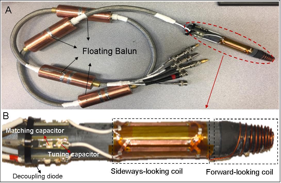
Sideways array design: A four-element phased-array sideways-looking coil was added for vaginal wall imaging. The coils, 140-mm long and 20-mm outer diameter, were wrapped at 90-degree increments around the pencil’s shaft (Fig. 2A, B).
Phantom experiments were performed in a 1.5T Siemens MR scanner with the array immersed in CuSo4 solution, mimicking the genitourinary environment. The endo-vaginal coil SNR was calculated, relative to the scanner’s 8-channel spine array. A swine experiment was performed to evaluate in-vivo performance. The coil was inserted into the vagina up to the cervix. High-resolution 2D and 3D Fast-Spin-Echo images (TR/TE/=2000ms/99ms, slice thickness=3 mm, resolution=0.47×0.47×3.00 mm3) were acquired in the coronal plane.
Results
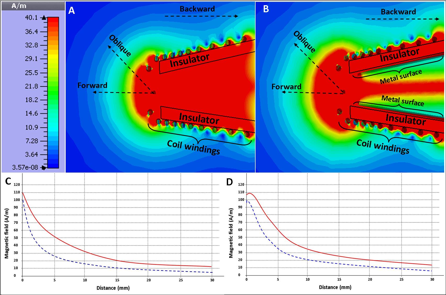
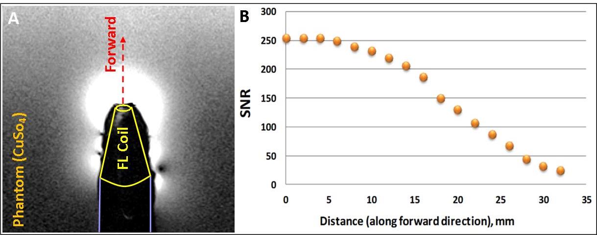
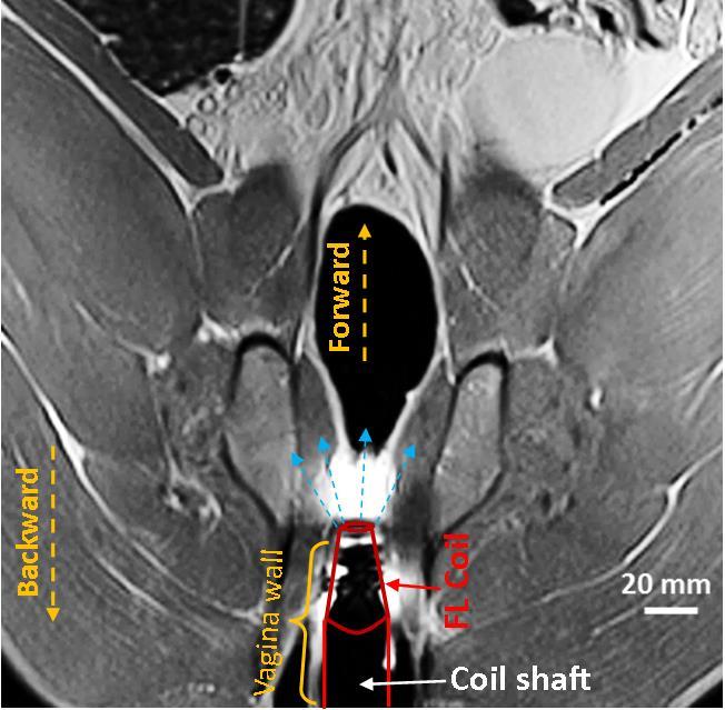
Figures 3A and 3B are simulated magnetic-field profiles for a metal-backed versus a non-metal backed construct. The field lines in the forward and oblique directions (Fig. 3C, D) extended further forwards in the metal-backed versus the non-metal-backed cases. Phantom Images acquired with the endo-vaginal coil (Fig 4A) closely correlated with the simulated RF profile. SNR values along the forward direction of the endo-vaginal coil were 4-8 times the spine array SNR over a 20-30 mm region (Fig 4B). In-vivo swine images acquired with the endo-vaginal coil demonstrated strong hyper-intensity above the vaginal canal (Fig 5).Conclusions
An endo-vaginal array was developed including a forward-looking coil that provided 4-8 times surface-coil SNR at distances of 20-30 mm above the coil. The array will be used during planning and radiation delivery. Future work will focus on clinical evaluation of the coil in cervical-cancer patients during MR-guided brachytherapy procedures.Acknowledgements
This study was supported by NIH R01-HL094610 and R21CA167800.References
[1] Viswanathan AN, Cormack R, Holloway CL, et al. Magnetic resonance-guided interstitial therapy for vaginal recurrence of endometrial cancer. International Journal of Radiation Oncology Biology Physics. 2006;66(1):91-99.
[2] Bayer (Medrad) transvaginal ecoil https://www.radiologysolutions.bayer.com/products/mr/mraccessories/ecoils/
[3] Downey K, Attygalle AD, Morgan VA, et al. Comparison of optimised endovaginal vs external array coil T2-weighted and diffusion-weighted imaging techniques for detecting suspected early stage (IA/IB1) uterine cervical cancer. Eur Radiol. 2016; 26: 941–950.
[4] Anderson KJ, Leung G, Dick AJ, et al. Forward-looking intravascular orthogonal-solenoid coil for imaging and guidance in occlusive arterial disease. Magn Reson Med. 2008;60(2):489-95.
Figures