0923
Frequency adjustable magnetic field probes1Department of Radiology - Medical Physics, Medical Center University of Freiburg, Faculty of Medicine, University of Freiburg, Freiburg, Germany
Synopsis
A new manufacturing method for the creation of magnetic field probes is presented. The method allows realizing field probes that can be frequency adjusted during MR acquisition. This opens up new possibilities for the use of field probes during MR experiments. In the presented proof-of-concept case, the field probe’s position in a standard gradient echo experiment was shifted within the field of view by changing its Larmor frequency using an additional micro-coil.
Purpose:
Magnetic
field probes have great potential to improve MRI measurements.[1]
Hydrogen-based field probes provide the highest signal but can
interfere with the imaging process. Therefore, fluorine, deuterium or
chemically-shifted field probes have been proposed.[2,3]
This work presents newly designed hydrogen-based field probes that
can be frequency adjusted during the measurement. Shifting the
working frequency of a field probe by a known offset can be useful in
many imaging settings. The
Larmor frequency can be changed, thus it is possible to avoid probe excitation
during RF transmission, in addition to the possibility of changing
the apparent position of the probe in frequency encoding direction.
This allows to
use hydrogen-based field probes in cases where the commonly used
fluorine-based field probes are impractical.Methods
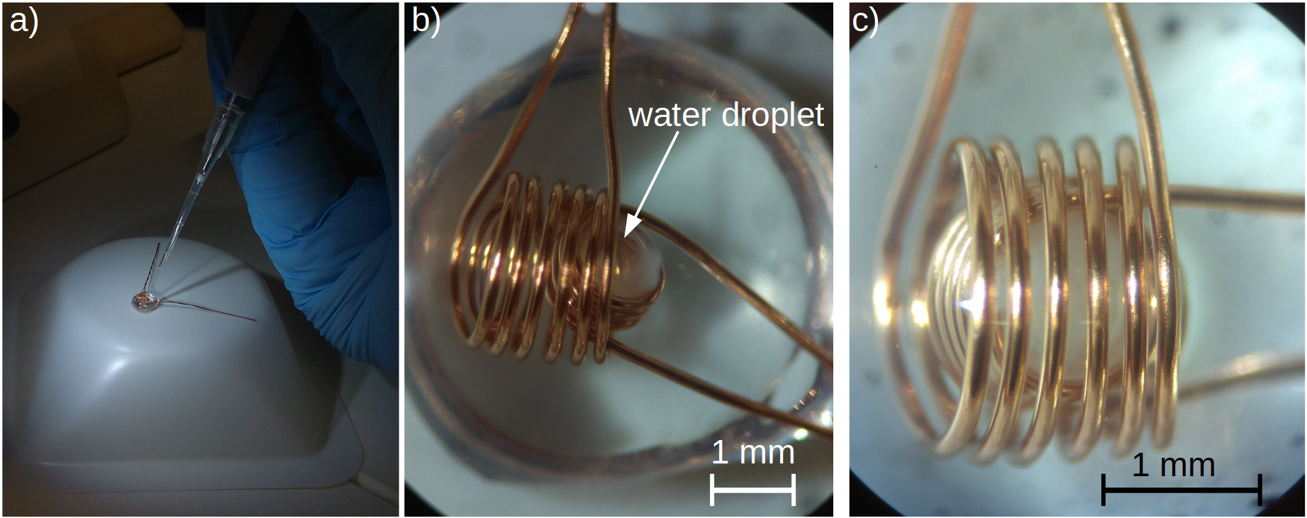
The probes were built in a bottom-up approach. First, a droplet of UV-curing-glue “Blufixx MGS” from BLUFIXX was cured under a UV-lamp. Then, the cured droplet was turned upside down and two coils (receive and B0-modification coils) were placed on top. The receive coil had an inner diameter of 1 mm whereas the orthogonally oriented outer coil had an inner diameter of 1.8 mm. Both coils were wound from enameled copper wire (diameter: 0.2 mm). A second glue droplet was placed on top of the two coils but not cured. A droplet of water was injected with a pipette as depicted in Figure 1. The 2.5 – 0.1 µl Eppendorf pipette was set to deposit 0.65 µl. Note, that due to the viscosity of the glue, the deposited volume deceeds the set volume. Subsequently the glue was optically cured. Additional layers of glue were applied in an iterative process of curing and adding glue until a spherical shape of the assembly was reached.
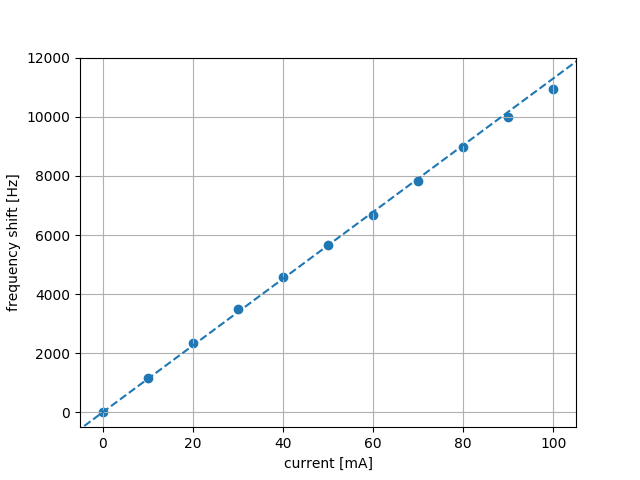
The frequency shift of the new magnetic field probe was measured with respect to the current flowing through the B0-modification coil. For each current setting the resonance peak’s maximum was evaluated in a 1H spectrum.
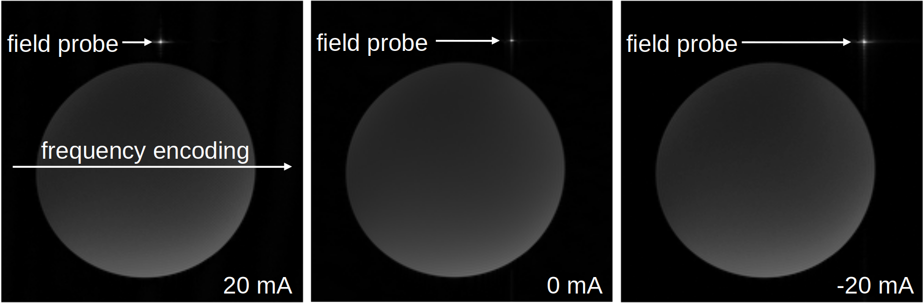
The gradient echo (GRE) measurements that were conducted to illustrate the shift in Larmor frequency of the new field probe were captured with a FOV 160 mm, FOV phase 100 %, slice thickness 20 mm, TR 100 ms, TE 6.45 ms and a bandwidth of 100 Hz per pixel.
Results and Discussion
Obtained
frequency shift results are depicted in Figure 2. The coil’s field
shows a linear characteristic in the measured range and exhibits a
slope of 113 Hz/mA.
Figure 3 illustrates the
shifted frequency of the field probe in the GRE measurement. The
numbers in the lower right corner indicate the current that was
flowing through the B0-modification
coil during the measurement. A current of I = 20 mA
shifts the field probe‘s apparent position to the left (in
frequency encoding direction) towards the top of the phantom. If the
current is inverted (I = - 20 mA),
the frequency shift appears to move the probe towards the right of
its actual position that is shown in the I = 0 mA
case. Currently the field probe is implemented as a solenoid
frequency modification coil. In future, Helmholtz or Maxwell designs
will be evaluated to allow for selective dephasing of the probe
signals if required by the target application. This eliminates the
need of using specialized field probes specifically doped on a
per-application basis.Conclusion
The resonance frequency of our proposed field probe can be changed by running a current through its B0 - modification coil. Changing the resonance frequency of magnetic field probes can be beneficial in manifold ways leading to a more flexible measurement design and eventually allowing the integration of probes with the RF coils or the gradient bore. Furthermore, concurrent measurements can be conducted at a shifted frequency to avoid interference with other MR measurements.Acknowledgements
The authors acknowledge Waldemar Schimpf for his excellent tooling expertise.References
1. Barmet et al. Spatiotemporal magnetic field monitoring for MR. Magn Reson Med 2008;60:187–197.
2. De Zanche et al. NMR Probes for Measuring Magnetic Fields. Magn Reson Med 2008;60:176-186.
3. Jorge J et al. Tracking discrete off-resonance markers. Magn Reson Med. 2018 Jan;79(1):160-171.
Figures