0792
MR Safety Watchdog for Safe Active Catheters: Wireless Impedance Controller with Real-time Feedback1Department of Radiology, Medical Physics, Medical Center ‐ University of Freiburg, Faculty of Medicine, University of Freiburg, Freiburg, Germany, 2German Cancer Consortium Partner Site Freiburg, German Cancer Research Center (DKFZ), Heidelberg, Germany, 3National Magnetic Resonance Research Center (UMRAM), Bilkent University, Ankara, Turkey, 4Physikalisch-Technische Bundesanstalt (PTB), Braunschweig and Berlin, Germany, 5Department of Electrical and Electronics Engineering, Bilkent University, Ankara, Turkey
Synopsis
RF-induced heating of implants or devices can be controlled through manipulation of their termination impedance which is dependent on the dielectric properties of the medium and the incident field configurations. We designed a wireless module that modifies the input impedance of an active catheter to keep the temperature increase below a threshold, ΔTmax. The wireless module monitors local heating at the tip of the catheter or can receive data from an external temperature measurement device to search for the optimal impedance that minimizes temperature rise. RF transmission is blocked via a feedback system when ΔTmax is exceeded.
Introduction
RF-induced heating of metallic implants or active devices is potentially dangerous for the patients during MR-guided interventions due to the interaction with the E fields of the MRI transmit coil with electrically conducting structures. Current standards for MR safety of such implants/devices assess their heating during worst-case RF field configurations, but these conditions can be impractical, and they may overestimate the heating risk. Therefore, a more realistic safety assessment is needed which includes real time monitoring of local tissue heating.
RF heating of linear structures such as wires can be controlled via their input impedance, Zin(1,2). However, ‘safe’ configurations are dependent on the dielectric properties of the surrounding medium and the incident field configurations, which can change during an intervention. Therefore, Zin should be dynamically adapted to the changes. In this study, a wireless module was designed that modifies Zin of an active catheter to keep the temperature increase, ΔT, below the pre-defined threshold, ΔTmax. An optimal Zin is searched that minimizes ΔT, and a feedback is sent to the MRI system to block the RF transmission when ΔTmax is exceeded. The MR safety watchdog is demonstrated at 3T with an active cardiovascular catheter.
Methods
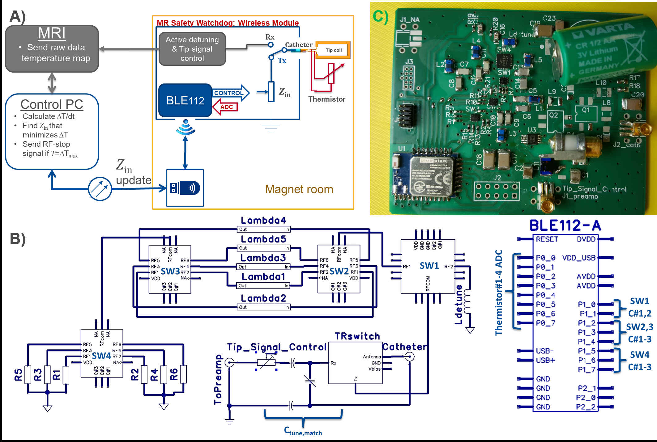
In Fig.1, a schematic and a photo of the wireless module is shown. Impedance control is activated during the Tx cycle (i.e., RF transmission). Impedance control is achieved by $$$n\lambda /24$$$ line ($$$n=1,2,...,5$$$) high-pass ‘tee’ circuits, and resistive loads, R1-6, which are selected by three SP6T switches (JSW6-33DR+, Mini-Circuits) as shown in Fig.2. One SPDT switch (HSWA2-30DR+, Mini-Circuits) is used to choose between the SP6T chain and an inductive termination used for active detuning. Tx/Rx mode switching is achieved by ADG918 (Analog Devices,Inc.) that is controlled by the active detuning signal provided by the MRI system. Temperature measurement network is established as in (3) and the coaxial cable of the catheter is used to connect the thermistor to the wireless module.
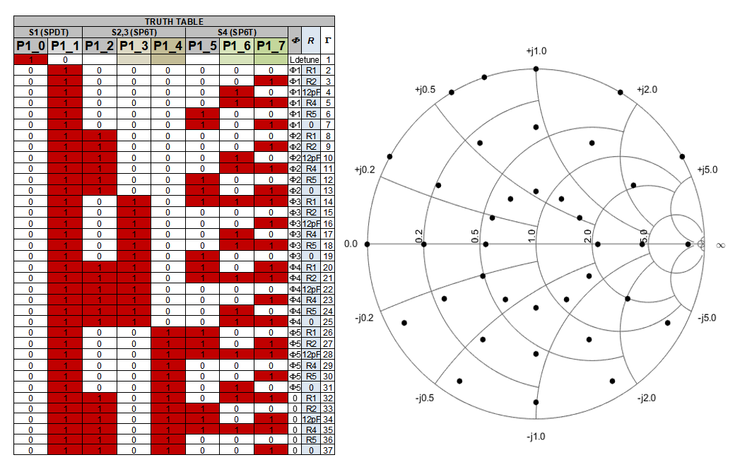
For the MR heating experiments, a threshold ΔTsetZ was chosen. The temperature is sampled every 1s for the thermistor, and 4s for the fiber optical setup. A java interface is designed to implement a gradient-descent optimization for adjustment of Zin. If during the iterations ΔTmax is reached, the feedback system sends a warning signal to stop the RF transmission. Truth table of the full switch settings and the reflection coefficients for the corresponding impedance values are shown in Fig.2.
For preliminary experiments, single SP6T switch with the following impedance options is used: 50Ω, 1000Ω, C=12pF, L=56nF, 0 Ω, C=12pF+λ/4. A 3T MRI system was used for the heating experiments (Siemens AG, Erlangen). A 110cm-long cardiovascular catheter, which had a saddle coil at the tip (1.6x18mm2) made of 35μm copper etched on flexible PCB substrate (thickness: 50μm) was constructed. The tip coil was connected to an interface circuit at the catheter end via a micro-coaxial cable (PicocoaxPCX40C05, Axon’Kabel). The catheter was partially immersed in a homogeneous ASTM phantom(4). When fiber optical temperature probes are used instead of the thermistor, the data is read from a log file.
Results
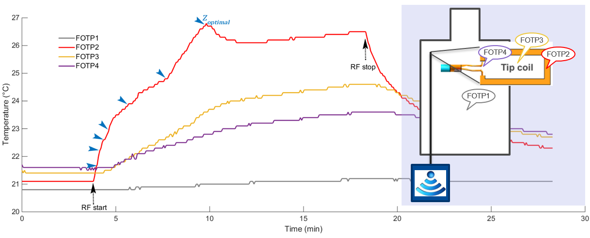
Results of the temperature measurements during a high SAR protocol (1.7W/kg) are shown in Fig.3. Manual change of Zin resulted in an instantaneous change of ΔT/dt(Fig.3). Here, time instants of the change of Zin are indicated by blue arrowheads. The starting impedance was 50Ω, and the Zoptimal was found as λ/8 line with R=0Ω at the terminal. The maximum temperature increase of 5.7°C was measured at the tip of the catheter, which was reduced to 5°C 90s after the Zoptimal was introduced. For Zoptimal, 0.001>ΔT/dt >-0.007°C/s, which is 98% slower than the initial value of 0.055°C/s.
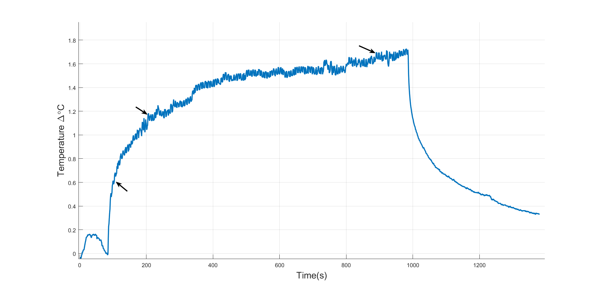
Temperature data acquired from another setting with the thermistor and catheter pair during the feedback mode are shown in Fig.4. 1.8°C of temperature increase was measured. The instants of automated change of Zin are indicated by the arrowheads when the MR safety watchdog is intervened.
Discussionand Conclusion
We presented a novel interface circuit for active catheters, which functions as a safety watchdog. Electrical control over both Rx and Tx cycles of a sequence is realized. Temperature measurements with manual impedance control shows that when an optimal value for Zin is set, the time to reach ΔTmax can be increased. Feedback algorithm is currently being investigated. The efficiency of the feedback mode could be better demonstrated with a worst-case scenario that results in higher temperature rise. More data needs to be collected to improve the feedback algorithm.
MR safety watchdog may not null the currents induced on the catheters (2), however: hazardous RF related heating problems during interventional procedures with active catheters can be potentially prevented using the proposed system. MR safety watchdog is vendor-independent.
Acknowledgements
No acknowledgement found.References
1. Silemek B, Açikel V, Yilmaz U, Atalar E. Wireless MR-Compatibility Control of Active Implantable Medical Devices. In: Proc. Intl. Soc. Mag. Reson. Med. 26. Paris, France; 2018. p. 644.
2. Özen AC, Lottner T, Bock M. Safety of active catheters in MRI: Termination impedance versus RF-induced heating. Magn. Reson. Med. 2018:1–12 doi: 10.1002/mrm.27481.
3. Silemek B, Acikel V, Oto C, et al. A temperature sensor implant for active implantable medical devices for in vivo subacute heating tests under MRI. Magn. Reson. Med. 2018;79:2824–2832 doi: 10.1002/mrm.26914.
4. American Society for Testing and Materials International. Designation: ASTM F2182-11a, standard test method for measurement of radio frequency induced heating near passive implants during magnetic resonance imaging. West Conshohocken, PA; 2011.
Figures