0791
Reconfigurable coil technology can substantially reduce RF heating of bilateral deep brain simulation leads during MRI at 1.5 T: First in-vitro studies with realistic implant trajectories1Northwestern University, Chicago, IL, United States, 2Department of Life Science Engineering, Institute of Medical Physics and Radiation Protection, Giessen, Germany, 3Massachusetts General Hospital, Charlestown, MA, United States, 4Albany Medical Center, Albany, NY, United States
Synopsis
Patients with deep brain stimulation (DBS) implants significantly benefit from MRI, however their access is restricted in these patients because of safety concerns due to RF heating of the leads. Recently we introduced a patient-adjustable reconfigurable MRI coil system that significantly reduced the SAR at the tip of single DBS leads (unilateral) in simulation studies during MRI at 1.5T. Here we present the first in-vitro measurements of RF heating-reduction performance of the coil system showing a significant reduction in heating of realistic bilateral DBS implants.
Introduction
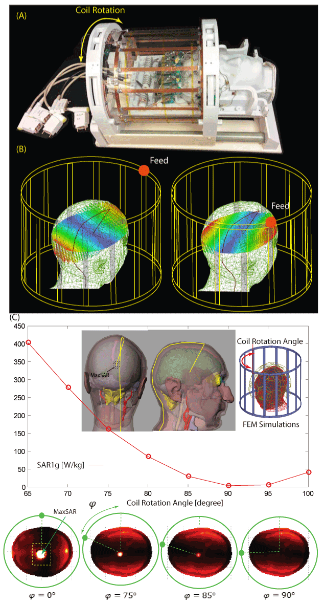
Patients with deep brain stimulation (DBS) implants significantly benefit from MRI, however access is restricted in these patients because of safety concerns due to RF heating of the leads. Recently we introduced a patient-adjustable reconfigurable MRI coil system to reduce the SAR at the tip of DBS leads during MRI at 1.5T 1,2. A simulation study with realistic models of single (unilateral) leads demonstrated that a substantial reduction in the local SAR up to 500-fold could be achieved compared to quadrature birdcage coils. Many patients however, have bilateral DBS implants3,4 and the question arises whether such reconfigurable coil system can be used for them, considering the fact that the optimum coil rotation angle to minimze the SAR is dependant on the lead trajectory. Here we present first in-vitro measurement results of temperature rise at the tips of bilateral DBS leads with realistic trajectories extracted from postoperative CT images of 10 patients using the rotating coil system. A total of 200 measurements were performed to record temperature rise during 2 minutes of RF exposure. In all patients, we were able to find an optimum coil rotation angle that reduced the heating of both left and right leads to a level below the heating produced by the body coil. An average heat reduction of 65% was achieved for bilateral DBS leads, suggesting reconfigurable coil technology is a promising approach for imaging of patients with DBS implants.Methods
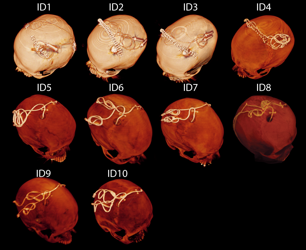
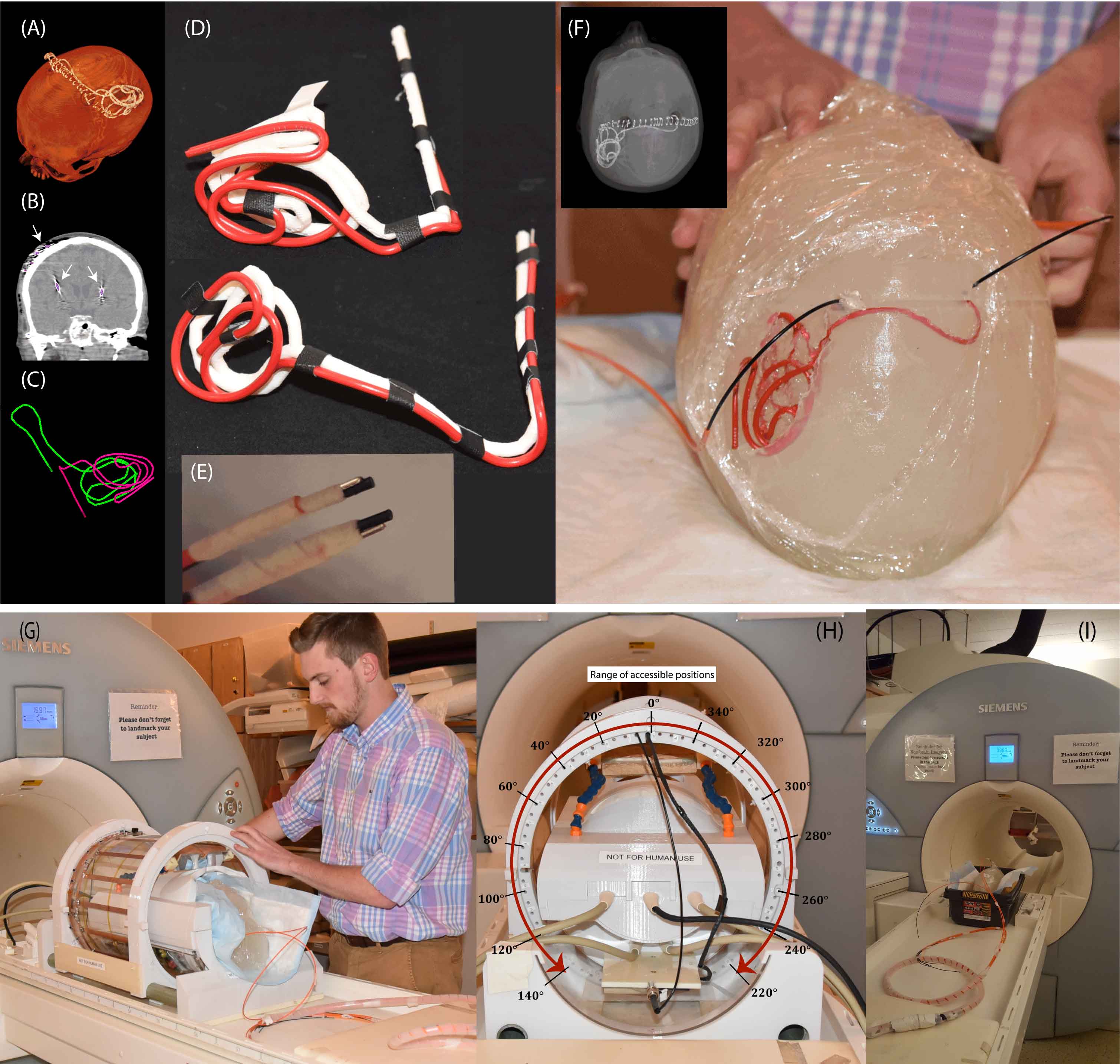
DBS leads and head phantoms Postoperative CT images of ten (10) patients were used to extract lead trajectories (Fig.2). 3D lead surfaces were segmented and exported to a CAD tool where trajectory lines were manually extracted, thickened (4mm), and 3D printed out of polycarbonate plastic. Two pieces of insulated wire (Ga 14, 40 cm long, 1cm exposed tip) were shaped around 3D printed guides. Wires were rigid enough to maintain their shape once they were routed around the plastic guides and were detached from the guide before being implanted into the head phantom (Fig.3A-D). An anthropomorphic head phantom was designed and 3D-printed based on the structural MRI of a healthy volunteer. The phantom was filled with agarose-doped saline solution (5L water, 14g NaCl) through a hole at the bottom. A relatively high percentage of agarose (4%) was used which resulted in a semi-solid gel to support the implants. Leads were implanted into the gel following the entrance point, angle, and trajectories as observed from CT images of the patient (Fig.3F). Fluoroptic temperature probes (OSENSA, BC, Canada) were secured at the exposed tips of the wires for temperature measurements.
RF exposure Experiments were performed at a 1.5T Magnetom Avanto system using the rotating coil and the scanner’s built-in body coil for comparison. The gradients were disabled and a train of 1ms rectangular RF pulses were transmitted for 120s with adjusted power such that both coils produced the same global SAR in the phantom. At the start of each experiment, temperature rise was measured at the tips of right and left implants while transmitting with the body coil. After measurements with the body coil, the phantom was left for 15 minutes to cool down and measurements with the rotating coil started with the coil at its default position (feed up, The coil was then rotated to the left at 20 increments until all accessible rotation angles from 0 to 140 were covered (Fig.3G-I). The coil was consequently repositioned at 0 and rotated to the other direction to cover angles from 360 -220 .
Results and Conclusion
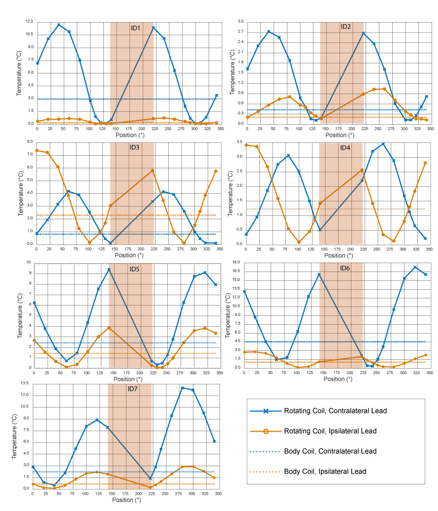
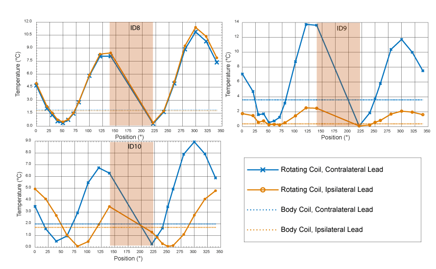
Figs.4 and 5 show the result of temperature rise at the tips of ipsilateral and contralateral leads for all accessible coil rotation angles. A substantial heat reduction of 80%±19% was achieved for single leads. In 33% of cases (patients 5,7 and 8) the optimum rotation angles that minimized the heating of ipsilateral and contralateral leads were the same. For the rest of cases, there was not an optimal angle that maximally reduced the heating of both leads. In all cases however, it was possible to find an intermediate coil position that reduced the heating of both leads to a level below the heating produced by a conventional body coil. When optimized for bilateral leads, an average heat reduction factor of 65%±25% was achieved. A closer look at cases where the same angle minimized the SAR for both left and right leads revealed that leads were routed substantially parallel in such cases. We recently showed that it is possible to instruct neurosurgeons to implement simulation-driven trajectories to enhance MR safety5. This will allow the reconfigurable coil system to perform as efficiently in the case of patients with bilateral leads as it does for unilateral implants.Acknowledgements
This work was supported by the NIH grant R00EB021320.References
1 Golestanirad, L. et al. Construction and modeling of a reconfigurable MRI coil for lowering SAR in patients with deep brain stimulation implants. Neuroimage 147, 577-588 (2017).
2 Golestanirad, L. et al. Feasibility of using linearly polarized rotating birdcage transmitters and close‐fitting receive arrays in MRI to reduce SAR in the vicinity of deep brain simulation implants. Magnetic resonance in medicine 77, 1701-1712 (2017).
3 Ondo, W., Almaguer, M., Jankovic, J. & Simpson, R. K. Thalamic deep brain stimulation: comparison between unilateral and bilateral placement. Archives of Neurology 58, 218-222 (2001).
4 Taba, H. A. et al. A closer look at unilateral versus bilateral deep brain stimulation: results of the National Institutes of Health COMPARE cohort. Journal of neurosurgery 113, 1224-1229 (2010).
5 Golestanirad, L. et al. RF-induced heating in tissue near bilateral DBS implants during MRI at 1.5 T and 3T: The role of surgical lead management. NeuroImage 184, 566-576 (2019).
Figures