0762
Prospective GIRF-based RF phase cycling to prevent eddy current-induced steady-state disruption in balanced SSFP imaging1Radiotherapy, University Medical Center Utrecht, Utrecht, Netherlands, 2MR Code BV, Zaltbommel, Netherlands
Synopsis
Balanced steady-state free precession sequences offer the highest signal-to-noise ratio and encode multiple physical parameters into the signal. However, the sequence is prone to eddy current-induced steady-state disruptions that can severely compromise the image quality or the physical parameter quantification. In this work we describe how the eddy currents act on the signal evolution and propose a novel prospective solution that in principle is applicable to any MRI examination.
Introduction
Balanced steady-state free precession (bSSFP) sequences offer the highest signal-to-noise ratio and encode multiple physical parameters into the signal. However, the sequence is prone to eddy current-induced steady state disruptions that can severely compromise the image quality or the physical parameter quantification. Bieri et al.1 showed that the eddy currents are a direct consequence of the gradient waveforms used for the spatial encoding. In particular, the gradients that change dynamically over sequence segments disrupt the steady-state (e.g. phase encode gradients), while the static gradients do not (e.g. slice-selection gradient). One strategy to reduce the impact of the eddy currents is to smoothly vary these gradient waveforms over the readouts, e.g. use paired or linear phase encoding schemes1. However, this strategy severely limits the choice of trajectories for bSSFP imaging2. Bieri et al. also proposed to annihilate the eddy current effect through partial slice dephasing (through-slice method). However, this method was confined to 2D. In this work we propose a model, based on the gradient impulse response function (GIRF)3 that predicts the impact of the eddy currents on the steady-state. Subsequently, we propose a novel prospective GIRF-based RF phase cycling scheme that exactly counteracts the eddy-current induced field modulations and therefore prevents steady-state disruptions.Material & Methods
Eddy currents and bSSFP signal model
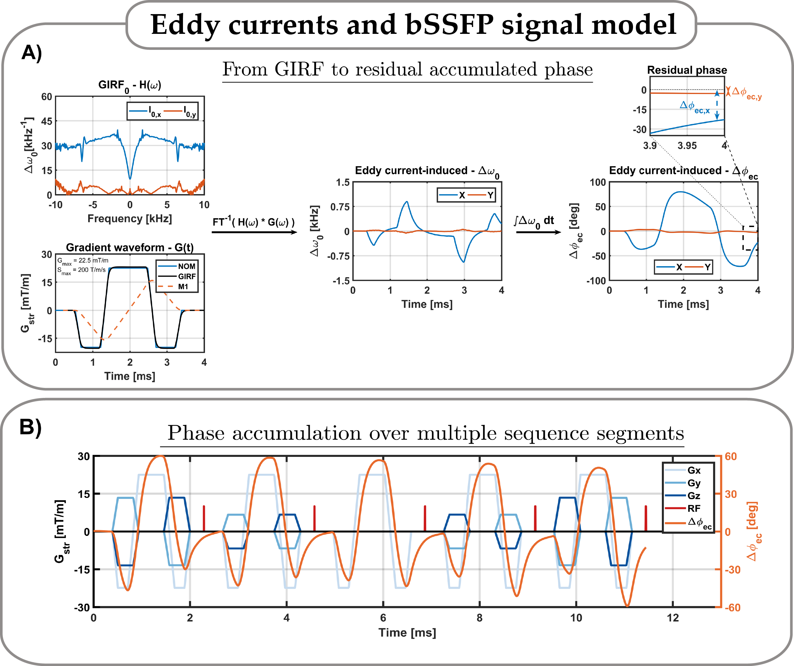
The interaction between the eddy currents and bSSFP signal model is illustrated in Fig.1-A. Zeroth and first order gradient impulse response functions (GIRF0,1) were measured using the thin slice method4,5. The GIRF0 induces a spatially uniform slowly decaying field modulation ΔB0(t) that accumulates additional phase with a residual term (ΔΦec(n)) at the end of the sequence segment n. The sequential RF pulse tips the magnetization which includes the ΔΦec(n) into the signal evolution, which is the root cause of the steady-state disruption (Fig.1-B). The ΔΦec(n) was used together with Bloch equations to simulate the signal evolution for varying off-resonances Δω0 in [-220 , 220]$ Hz.
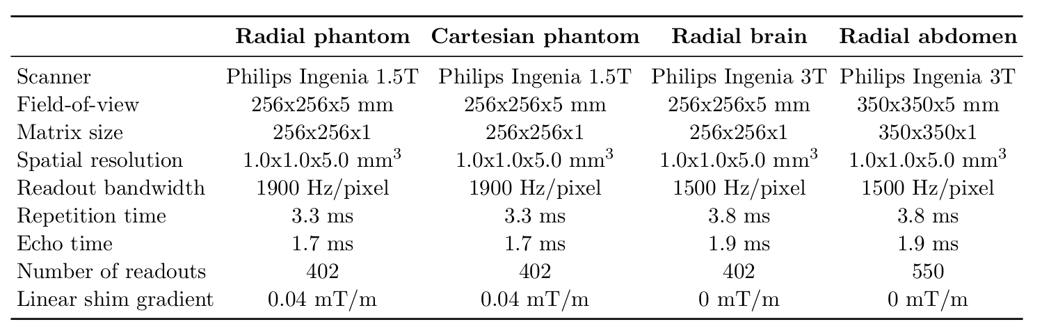
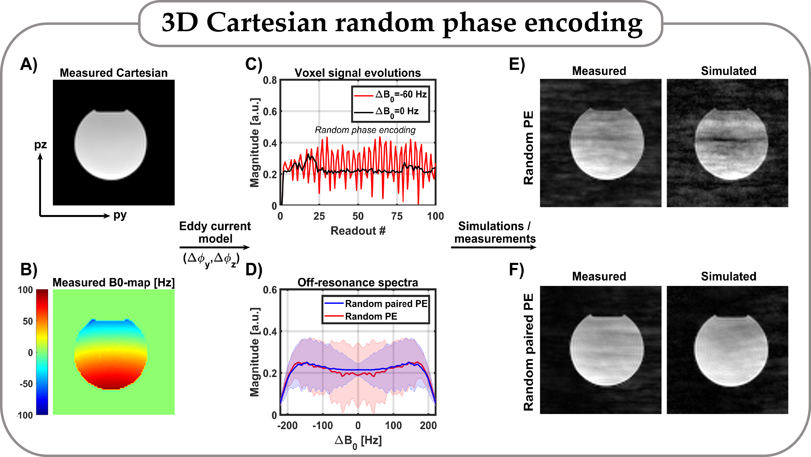
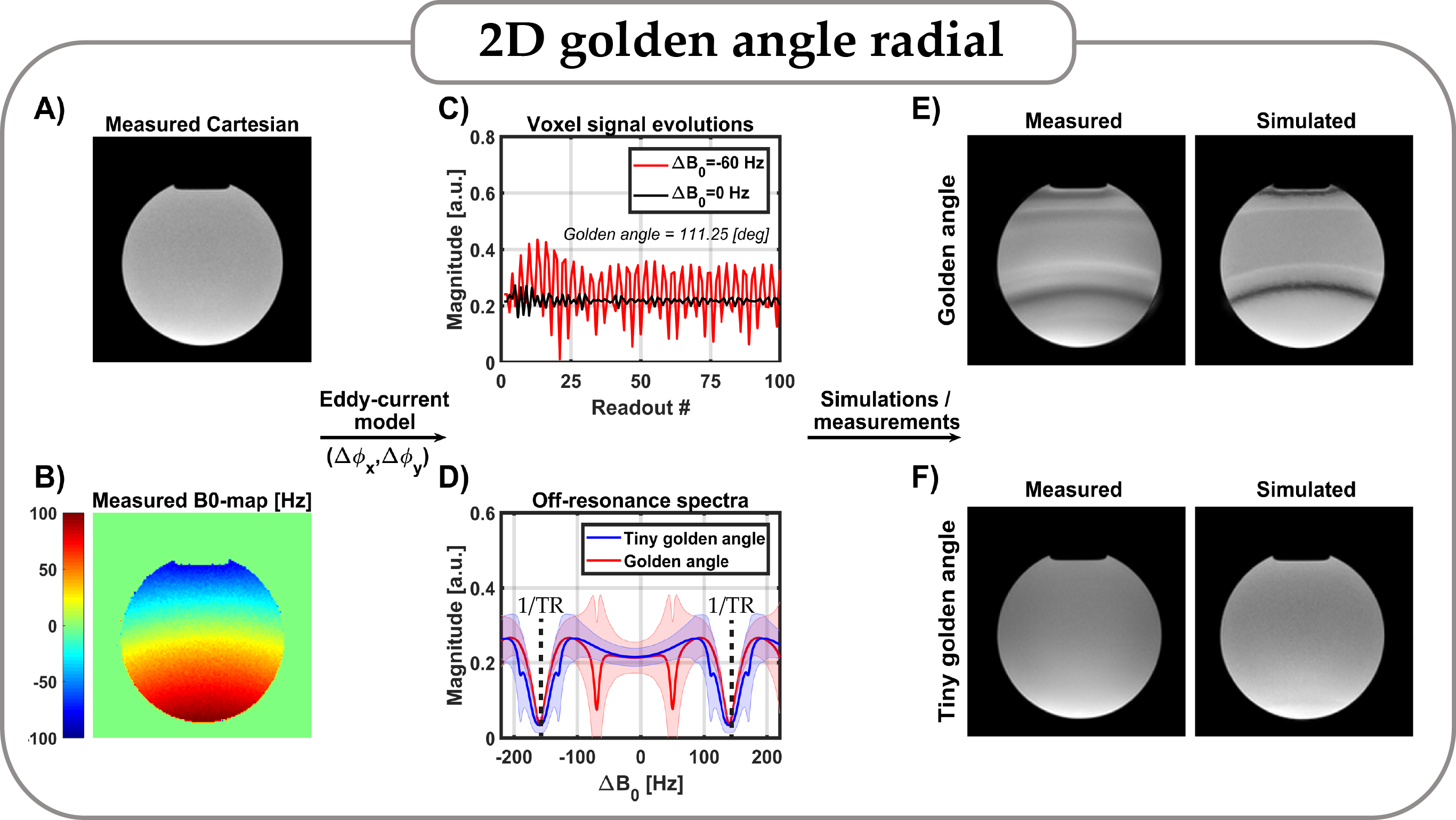
To validate the capability of the model to predict image artefacts due to the steady-state disruptions we acquired two phantom datasets. Both datasets were acquired with a linear shim gradient enabled to illuminate the signal response for varying off-resonance. Dataset 1: 3D Cartesian data with random phase encodes or random paired phase encodes1. Dataset 2: 2D Radial data with golden angle (GA) (111.2°) or tiny golden angle (tGA) (23.6°) angular increments6,7. Sequence parameters are shown in Fig.2.
Prospective RF phase cycling
The proposed model implies that the effects of the eddy currents are spatially uniform and manifest as additional phase accumulations. These effects can be compensated by anticipating the phase accumulation and adjusting the phase of the next RF pulse. The RF phase cycle (RF-PC) scheme then becomes a function of the gradient waveform.
\begin{eqnarray}\Delta\phi_{ec}(n) = \sum_{ax \in x,y,z}\int_0^{TR} G_{ax}(n,t) * GIRF_{0,ax}(t) dt\end{eqnarray}
Here, Gax(n,t) is the gradient waveform for segment n and axis ax and GIRF0,ax(t) is the 0th order impulse response for axis ax in the time domain. To validate the prospective RF-PC method we acquired in vivo data with 2D GA sampling in the abdomen and the brain. Sequence parameters are shown in Fig.2.
Results
bSSFP signal model validation
The simulated and measured images of the Cartesian dataset are in good agreement for both the paired and non-paired scans (Fig-3). The random phase encoded scan induced considerably more artefacts then the paired random phase encodes scan. The simulated and measured images of the radial dataset are in good agreement for both GA and tGA scans (Fig-3). The simulated bSSFP signal profile differed considerably between GA and tGA (Fig-4). For the GA case a second pair off “bands” appeared, which clearly manifests in both the measured and simulated images.
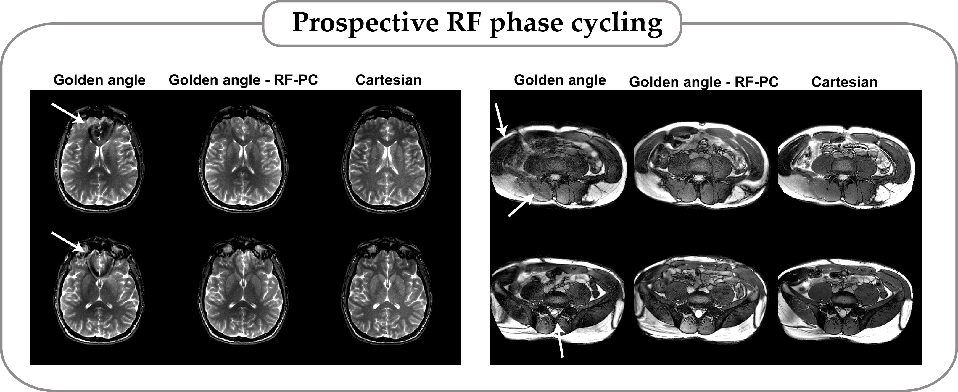
Prospective RF phase cycling
The GA acquisition shows signal voids in the images, which are not present in the Cartesian scan (Fig-5). These voids are removed when the GA data is acquired with the RF-PC scheme, in both the brain and abdomen data. Note that the RF-PC reconstructions have considerably improved image uniformity.
Discussion & conclusion
We showed that the zeroth order gradient impulse response function is the primary factor to predict eddy current-induced steady-state disruption in bSSFP imaging. The severity of disruption strongly depends on the local off-resonance frequency. We show that the steady-state can be maintained by prospectively adapting the RF phase to counter-act the eddy current-induced phase accumulation. We believe that this novel correction method will improve the robustness of bSSFP imaging for routine clinical usage and may have considerable impact on the parameter quantification in magnetic resonance fingerprinting8.Acknowledgements
This work is part of the research program HTSM with project number 15354, which is (partly) financed by the Netherlands Organization for Scientific Research (NWO).Bjorn Stemkens declares to be a majority shareholder of MRCode BV. Rob Tijssen and Cornelis van den Berg declare to be a minority shareholder of MRCode BV.References
1 O. Bieri et al., Analysis and compensation of eddy currents in balanced SSFP. Magn Reson Med. 2005 Jul;54(1):129-37.
2 B.A. Jung et al., Breathhold 3D-TrueFISP Cine Cardiac Imaging. Magnetic Resonance in Medicine 48:921–925 (2002)
3 S.J. Vannesjo et al., Gradient system characterization by impulse response measurements with a dynamic field camera. Magn Reson Med. 2013 Feb;69(2):583-93.
4 J.H. Duyn et al., Simple Correction Method fork-Space Trajectory Deviations in MRI. J Magn Reson. 1998 May;132(1):150-3.
5 E.K. Brodsky et al. Rapid Measurement and Correction of Phase Errors from B0 Eddy Currents: Impact on Image Quality for Non-Cartesian Imaging. Magn Reson Med. 2013 Feb; 69(2): 509–515.
6 S. Winkelmann et al., An optimal radial profile order based on the Golden Ratio for time-resolved MRI. IEEE Trans Med Imaging. 2007 Jan;26(1):68-76.
7 S. Wundrak et al., Golden ratio sparse MRI using tiny golden angles. Magn Reson Med. 2016 Jun;75(6):2372-8.
8 D. Ma et al., Magnetic Resonance Fingerprinting. Nature volume 495, pages 187–192 (14 March 2013)
Figures