0757
Deep reinforcement learning designed RF pulse1Department of Electrical and Computer Engineering, Seoul National University, Seoul, Korea, Republic of, 2Department of Biomedical Engineering, Hankuk University of Foreign Studies, Gyeonggi-do, Korea, Republic of
Synopsis
In this study, we developed an approach
Introduction
Recently, deep learning has found a new application of generating a machine-optimized MRI pulse sequence1. This approach may have potential of creating an optimized solution beyond human intuition. Inspired by the work, we developed a novel approach of designing an RF pulse using deep reinforcement learning (DRL)2.Methods
[Multi-band RF] Design of a high TBW/multiband factor RF pulse often suffers from a long pulse duration or high peak amplitude. For example, a cosine-modulated SLR refocusing pulse with TBW=4, multiband factor (MF)=5, and 1% ripple takes 21.4 ms to satisfy the peak RF constraint (0.2 G). Human intuition-based approach such as phase-optimization3 or search algorithm-based approaches including time-shift4 and root-flipping5 have been proposed to optimize the design. These methods may provide a good solution for small TBW and/or MF but may not find an optimal solution for large TBW and/or MF.
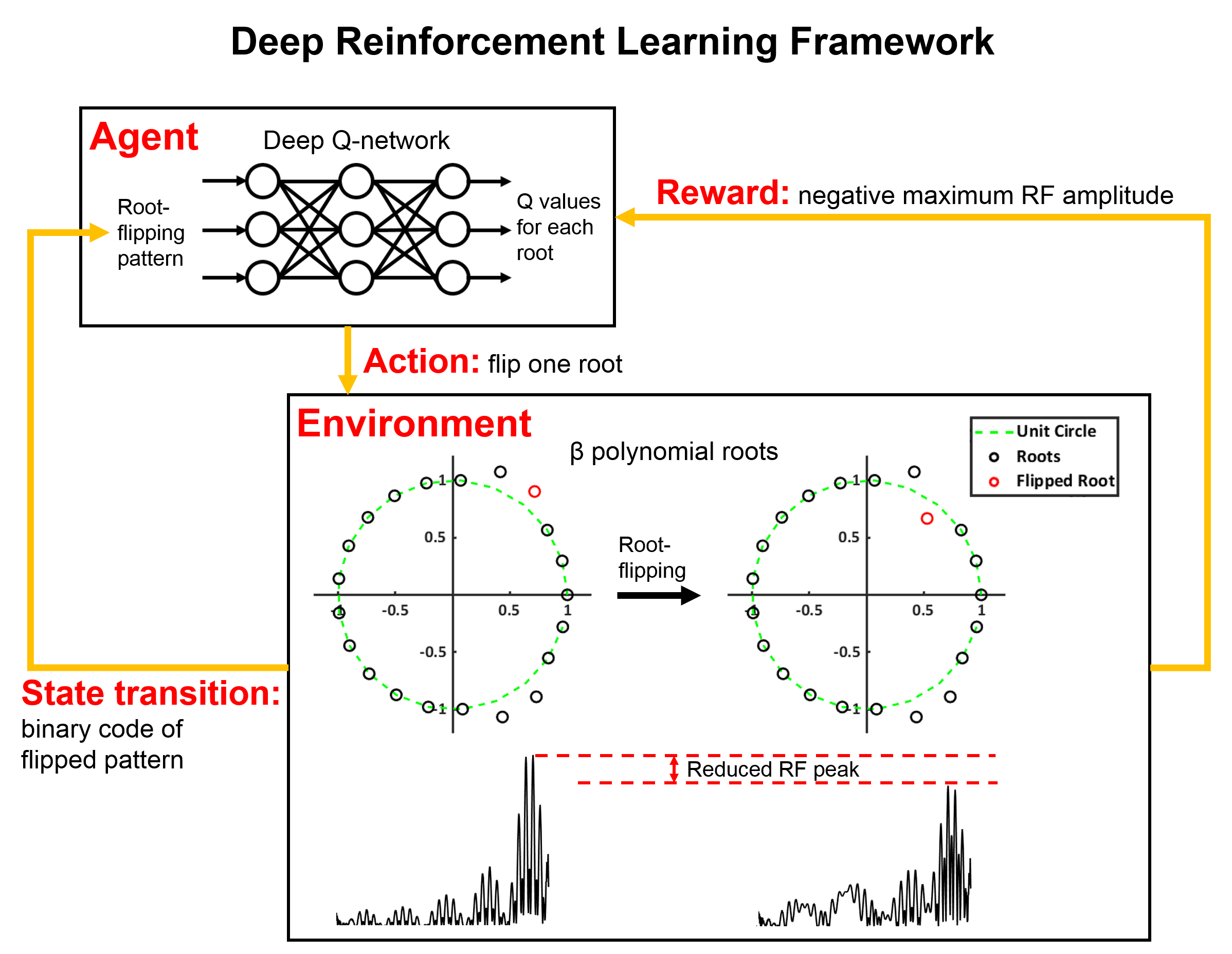
[Root-flipping in SLR] In SLR algorithm, an RF pulse design is transformed to a filter design6 and root-flipping has shown to change the RF shape and slice phase profile without modifying the magnitude profile (Fig. 1). The modified phase profile can be compensated for linear-phase by designing a 90º&180º pulse pair for spin-echo imaging7,8. Hence, the RF pulse design becomes finding an optimum root-flipping pattern for a target design (e.g. minimum peak RF). When designing an RF with high TBW and/or high MF, the number of roots becomes too many to find an optimal solution using exhaustive search (e.g. TBW = 6 and MF = 5 yields 231 possible combinations!). To address this challenge, we adopted the DRL framework2.
[Deep reinforcement learning] DRL trains a deep neural network to make a sequence of decisions. It has two main components: agent and environment. The agent tries to learn an optimized strategy in the environment to maximize the total reward. In our RF design, a neural network (i.e. agent) flips one of the roots in each trial (i.e. change the state of the environment) to reduce peak RF amplitude (i.e. maximize reward). Then the network is updated in each flipping according to the loss (see [2] for loss). The reward is defined as the negative maximum RF amplitude. This reward induces the agent to find a lower maximum peak RF because the agent gets a negative feedback (i.e. penalty; higher maximum RF means larger penalty) at each action and tries to reduce sum of penalties by moving toward better solutions. For our design, deep Q-learning was utilized2. To avoid rapid phase modulation, roots are inside and outside of unit circle symmetrically around the real axis9.
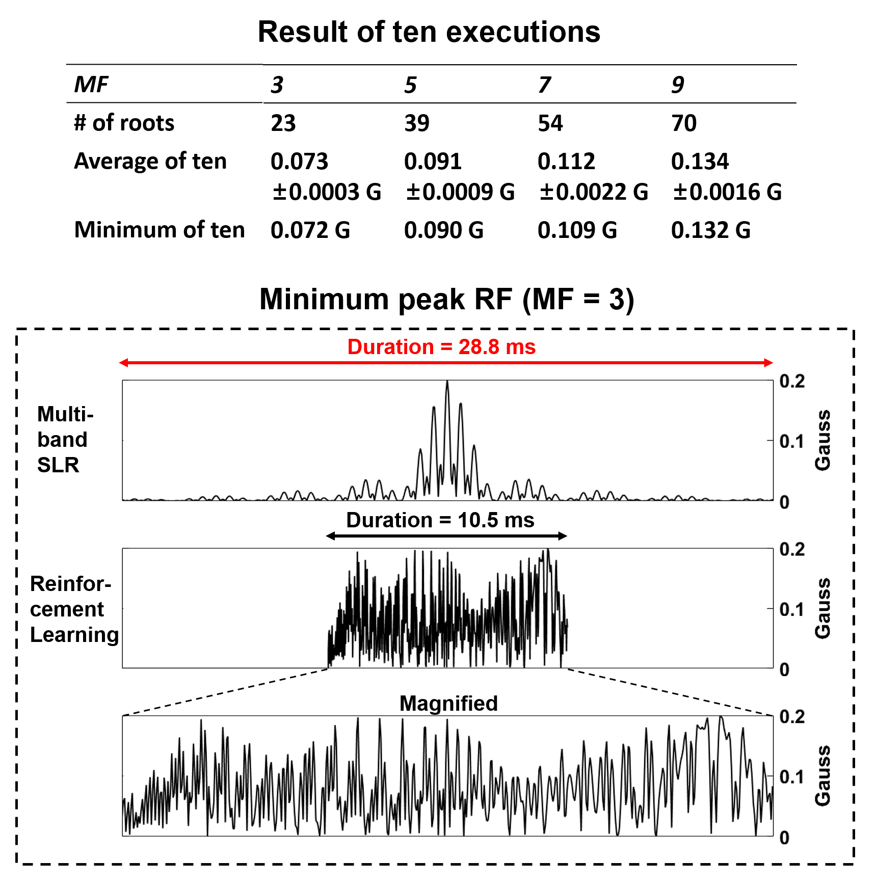
[Simulation] Four multiband refocusing RF pulses (MF=3,5,7, and 9, TBW=8 and band separation (BS)=6 times of slice width) were generated using the DRL algorithm. The algorithm was terminated when the peak was not reduced for 10,000 iterations. The design was repeated ten times to test the consistency of the solution. A matched excitation RF was designed as in [7,8]. For comparison, a cosine-modulated SLR pulse of the same specification was designed. All pulses were scaled to have the minimum duration for a given maximum RF constraint (0.2 Gauss).
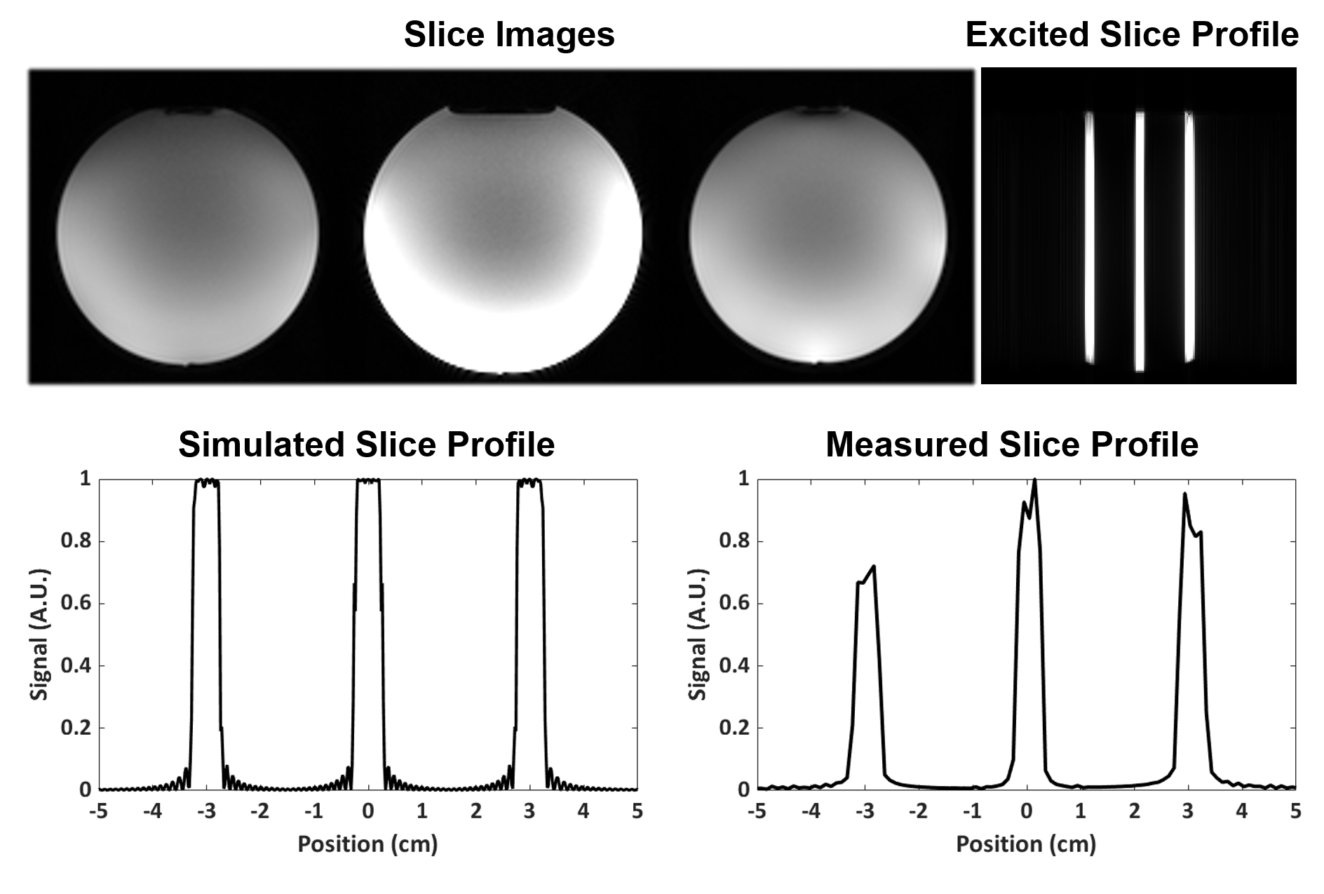
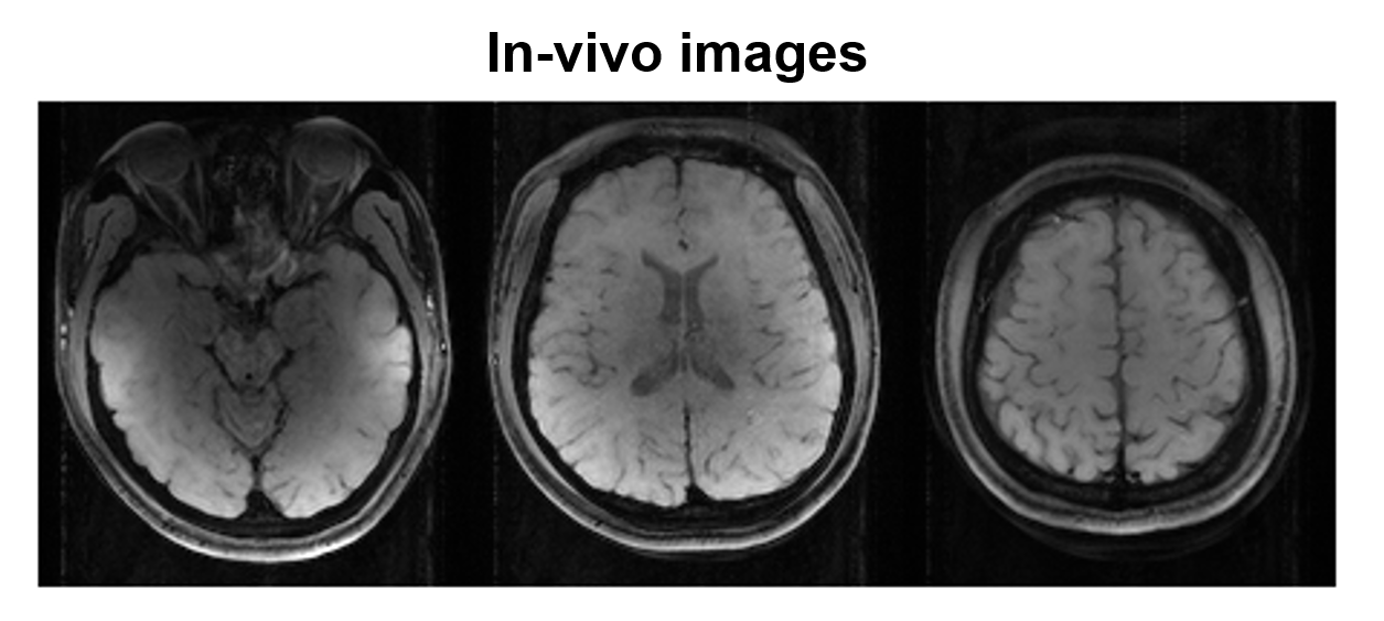
[MRI scans] A spherical water phantom was scanned at 3T using one of the DRL-optimized pulse (MF=3, TBW=8, and BS=6). The overlapped slices were unfolded by [10]. The scan parameters were TR/TE=500/22ms, voxel size=1.5x1.5mm2, and thickness=5mm. The excited slice profile was visualized by imaging an orthogonal plane to the slice selection. Additionally, an in-vivo scan was performed with the same pulse. The scan parameters were TR/TE=1000/22ms, voxel size=1.2x1.2mm2, and thickness=5mm.
Results
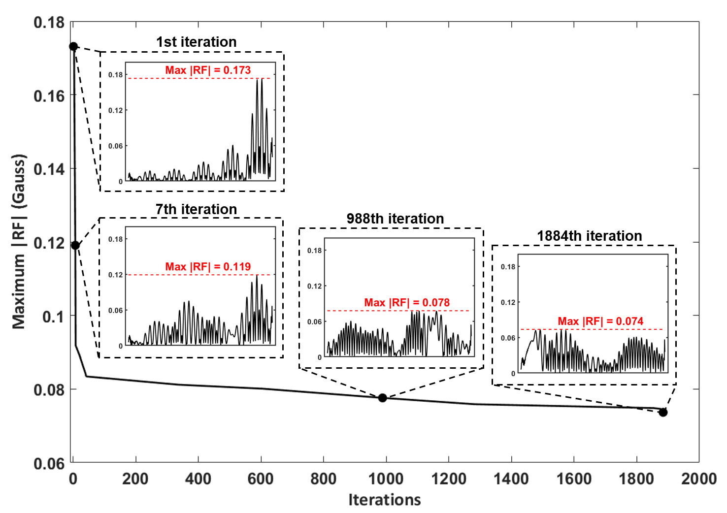
Figure 2 shows the progression of the DRL-designed RF pulse over the iterations. As the iteration progresses, the peak RF was reduced and the RF energy was spread out over the RF duration. When the ten repetitive designs were compared, the results showed good consistency with small standard deviation (Fig. 3). The duration of the DRL-designed RF (10.5 ms) was 2.7 times shorter than that of the cosine-modulated pulse (28.8 ms) for MF=3. The phantom results (Fig. 4) demonstrate well-matched slice locations between the simulation and experiment. The signal intensity variation may be explained by uncorrected coil sensitivity and/or the errors from the rapid amplitude swing11. The in-vivo result demonstrates the feasibility of the DRL-design pulse (Fig. 5).Discussion and Conclusions
In this work, we proposed a new RF design algorithm using a deep neural network. The DRL-optimized RF pulse had much shorter duration than the modulated SLR pulse.Acknowledgements
This work was supported by the Brain Korea 21 Plus Project in 2018. This work was supported by Samsung Research Funding & Incubation Center of Samsung Electronics under Project Number SRFC-IT1801-09.References
[1] Zhu, Bo, et al. AUTOmated pulse SEQuence generation (AUTOSEQ) using Bayesian reinforcement learning in an MRI physics simulation environment, In Proceedings of the 26th Annual Meeting of ISMRM, Paris, France, 2018.
[2] Mnih, Volodymyr, et al. "Human-level control through deep reinforcement learning." Nature 518.7540 (2015): 529.
[3] Wong EC. Optimized phase schedules for minimizing peak RF power in simultaneous multi-slice RF excitation pulses. In Proceedings of the 20th Annual Meeting of ISMRM, Melbourne, Australia, 2012. p.2209
[4] Auerbach, Edward J., et al. "Multiband accelerated spin‐echo echo planar imaging with reduced peak RF power using time‐shifted RF pulses." Magnetic resonance in medicine 69.5 (2013): 1261-1267.
[5] Sharma, Anuj, Michael Lustig, and William A. Grissom. "Root‐flipped multiband refocusing pulses." Magnetic resonance in medicine 75.1 (2016): 227-237.
[6] Pauly, John, et al. "Parameter relations for the Shinnar-Le Roux selective excitation pulse design algorithm (NMR imaging)." IEEE transactions on medical imaging 10.1 (1991): 53-65.
[7] Zun Z, Hargreaves BA, Pauly JM, Zaharchuk G. Near-contiguous spin echo imaging using matched-phase RF and its application in velocity-selective arterial spin labeling. Magn Reson Med 2014;71:2043–2050.
[8] Balchandani P, Khalighi MM, Glover G, Pauly JM, Spielman DM. Self-refocused adiabatic pulse for spin echo imaging at 7T. Magn Reson Med 2012;67:1077–1085.
[9] Abo Seada, Samy, et al. "Optimized amplitude modulated multiband RF pulse design." Magnetic resonance in medicine 78.6 (2017): 2185-219
[10] Blaimer, Martin, et al. "Accelerated volumetric MRI with a SENSE/GRAPPA combination." Journal of Magnetic Resonance Imaging: An Official Journal of the International Society for Magnetic Resonance in Medicine 24.2 (2006): 444-450.
[11] Stang PP, Kerr AB, Grissom WA, Pauly J, Scott G. Vector Iterative Pre-Distortion: An Auto-calibration Method for Transmit Arrays. In Proceedings of the 17th Annual Meeting of ISMRM, Honolulu, Hawaii, USA, 2009. p. 395.
Figures