0732
A New Coil Element for Highly-Dense Transmit Arrays : An Introduction to Non-Uniform Dielectric Substrate (NODES) Antenna1Electrical and Electronics Engineering, Bilkent University, Ankara, Turkey, 2Center for Magnetic Resonance Research, University of Minnesota, Minneapolis, MN, United States, 3Department of Engineering Science and Mechanics, The Pennsylvania State University, University Park, PA, United States, 4National Magnetic Resonance Research Center (UMRAM), Ankara, Turkey
Synopsis
Ultra-high field (UHF)-magnetic resonance imaging (MRI) provides numerous benefits such as a significant increase in signal-to-noise ratio (SNR) however, the local specific absorption rate (SAR) becomes a limiting factor in many applications. Utilizing a proper TxArray coil with an adequate number of elements and improved SAR performance may provide a good solution for this issue. In this work, we propose to use a short antenna with a Non-uniform Dielectric Substrate (NODES) which provides an opportunity to design a highly-dense TxArray with improved SAR performance.
Introduction
Transmit array (TxArray) technology is essential to manage SAR and to take full advantage of UHF-MRI[1,2]. Previous studies [3] demonstrated the impact of increasing the number of transmit elements in an array for improving SAR performance as well as flip angle homogeneity. However, the size of the elements and coil coupling pose practical limitations on the maximum number of elements that can be used in a TxArray. Recently, fractionated dipoles [4,5], snake antennas[6], and bumped dipoles/loops[7] were proposed for UHF MR imaging. In this study, we propose a new dipole antenna design utilizing a non-uniform dielectric substrate placed underneath the element in order to optimize SAR efficiency. This modification increases the uniformity of the current distribution on the dipole and reduces local SAR. As a result, it enables us to design highly-dense transmit arrays using shorter elements. For proof of concept, we performed an optimization on a dipole at 10.5 T using EM simulations. In addition, we constructed the corresponding structure and conducted a phantom experiment on a whole-body 10.5 T scannerTheory and Methods
Decreasing the length of a dipole forces the current to rapidly decrease towards the ends (current vanishes at the two ends of the dipole due to the high impedances at these points). On the other hand, based on Maxwell’s equations, the transverse electric field and SAR in the tissue is elevated when the current rapidly changes along the conductor. Placing high-permittivity blocks at two ends of the dipole can potentially increase the effective capacitance between these points and the body. As a result, the corresponding impedance can be reduced. This effect in turn, increases the uniformity of the current on the dipole and reduces the electric fields. On the other hand, the B1+ generated by this current becomes considerably uniform along the z-direction. The following parameters were optimized in order to maximize peak 10g SAR efficiency: length of the dipole, relative permittivity of the substrate, the blocks at two ends of the dipole, and the block at the feed-point, the height of the blocks and the width of the dipole at two ends. Optimization goal for the design process is summarized below:
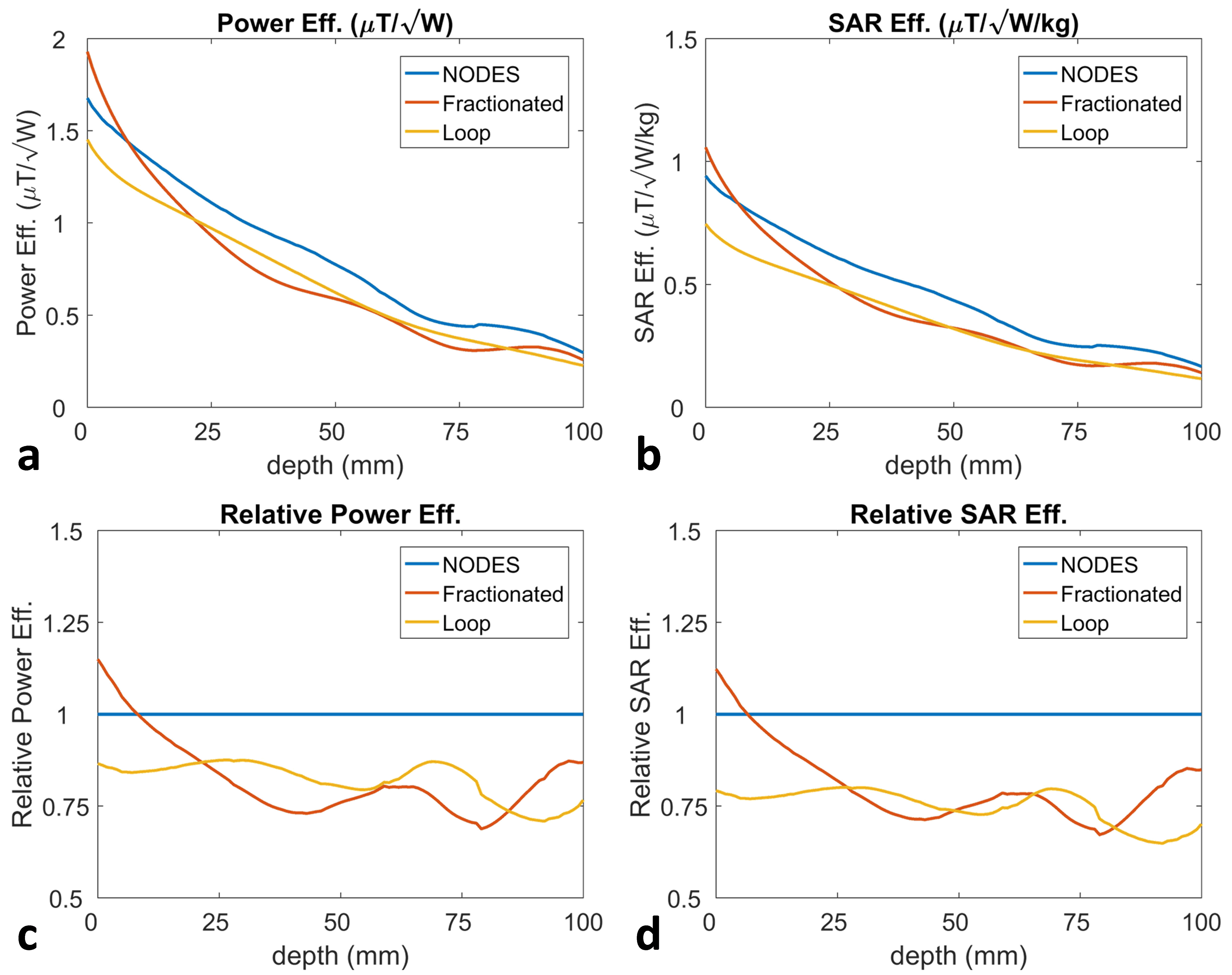
maximize mean {10 g SAR efficiency at the depth of 50 to 100 mm}
We performed 8575 fast simulations with a finite-element method (FEM)-based EM simulator (HFSS, ANSYS, Canonsburg, PA, USA). As a result of the optimization, a non-uniform dielectric substrate (NODES) antenna was designed. Fig.1a-c, shows the optimized NODES antenna, fractionated dipole and the loop. For the experimental setup, we employed a high-dielectric constant block made of TiO2 (εr=100, σ=1.1 mS/m) in construction of the NODES antenna (Fig. 2a). Polyethylene terephthalate glycol (PETG) with εr=2.4, σ=0.6 mS/m used for the rest of the block. For the fractionated dipole, conductors were located on FR4 PCBs which were mounted on 10 mm-thick thermoplastic polyetherimide blocks (ULTEM 1000 resin, Sabic Global, Pittsfield, MA). In experiments (Fig2b), the NODES antenna was placed 230 mm away from the fractionated dipole, on the phantom. The MRI experiments were conducted on a 10.5T whole-body scanner (Siemens Healthcare, Erlangen, Germany). B1-maps were obtained using the actual flip-angle imaging [8] (AFI) technique. Temperature mapping was performed based on the proton resonance offset method [9,10] with a multi-echo gradient-echo pulse sequence.
Results
Fig.3 shows the power and SAR efficiencies (absolute and relative) of the three transmitters sampled on a line perpendicular to the elements. Fig.4 shows the power-efficiency and SAR maps, obtained from EM simulations and MR measurements. For depths of 5 and 10 cm inside the body, > 30% improvements in SAR efficiency are observed.
Conclusion
We introduce the NODES antenna, a short dipole with improved SAR performance mounted on a block with non-uniform dielectric constant. Because of the reduced size of the element, NODES can be used to construct highly dense transmit arrays. As proof of concept, we constructed a NODES antenna and performed EM simulations and MRI experiments with a 10.5T scanner. Results show that the SAR efficiency can be improved by > 30 % compared to a loop and fractionated dipole.Acknowledgements
This work was supported by following grants: NIBIB P41 EB015894, NIH S10 RR029672, NIH- U01 EB025144.References
1. Adriany G, Van de Moortele PF, Wiesinger F, Moeller S, Strupp JP, Andersen P, Snyder C, Zhang X, Chen W, Pruessmann KP, Boesiger P. Transmit and receive transmission line arrays for 7 Tesla parallel imaging. Magnetic Resonance in Medicine: An Official Journal of the International Society for Magnetic Resonance in Medicine. 2005 Feb;53(2):434-45.
2. Metzger GJ, Snyder C, Akgun C, Vaughan T, Ugurbil K, Van de Moortele PF. Local B1+ shimming for prostate imaging with transceiver arrays at 7T based on subject‐dependent transmit phase measurements. Magnetic Resonance in Medicine: An Official Journal of the International Society for Magnetic Resonance in Medicine. 2008 Feb;59(2):396-409.
3. Lattanzi R, Wiggins GC, Zhang B, Duan Q, Brown R, Sodickson DK. Approaching ultimate intrinsic signal‐to‐noise ratio with loop and dipole antennas. Magnetic resonance in medicine. 2018 Mar;79(3):1789-803.
4. Raaijmakers AJ, Italiaander M, Voogt IJ, Luijten PR, Hoogduin JM, Klomp DW, van Den Berg CA. The fractionated dipole antenna: A new antenna for body imaging at 7 T esla. Magnetic resonance in medicine. 2016 Mar;75(3):1366-74.
5. Ertürk MA, Wu X, Eryaman Y, Van de Moortele PF, Auerbach EJ, Lagore RL, DelaBarre L, Vaughan JT, Uğurbil K, Adriany G, Metzger GJ. Toward imaging the body at 10.5 tesla. Magnetic resonance in medicine. 2017 Jan;77(1):434-43.
6. Steensma B, Andrade AV, Klomp DW, Van den Berg CA, Luijten PR, Raaijmakers AJ. Body imaging at 7 Tesla with much lower SAR levels: an introduction of the Snake Antenna array. InInternational Society of Magnetic Resonance in Medicine 23rd Annual Meeting & Exhibition 2016 (p. 0395).
7. Sadeghi-Tarakameh A, Torrado-Carvajal A, Ariyurek C, Atalar E, Adriany G, Metzger GJ, Lagore RL, DelaBarre L, Grant A, Van de Moortele PF, Ugurbil K, Eryaman Y. Optimizing the topography of transmit coils for SAR management.
8. Yarnykh VL. Actual flip‐angle imaging in the pulsed steady state: a method for rapid three‐dimensional mapping of the transmitted radiofrequency field. Magnetic Resonance in Medicine: An Official Journal of the International Society for Magnetic Resonance in Medicine. 2007 Jan;57(1):192-200.
9. Poorter JD, Wagter CD, Deene YD, Thomsen C, Ståhlberg F, Achten E. Noninvasive MRI thermometry with the proton resonance frequency (PRF) method: in vivo results in human muscle. Magnetic resonance in medicine. 1995 Jan 1;33(1):74-81.
10. 15. Kuroda K, Oshio K, Chung AH, Hynynen K, Jolesz FA. Temperature mapping using the water proton chemical shift: a chemical shift selective phase mapping method. Magnetic resonance in medicine. 1997 Nov 1;38(5):845-51.
Figures