0728
Parallel transmission medical implant safety testbed: First application using time-domain E-field probes to measure and mitigate RF induced currents1Physikalisch-Technische Bundesanstalt (PTB), Braunschweig and Berlin, Germany
Synopsis
A parallel transmission (pTx) implant safety testbed has been developed, that allows to investigate manifold MR safety related scenarios. The testbed can be used to investigate sensor-feedback methods, perform validation measurements of MR based current detection methods and investigate the MR safety of a variety of implants for various clinical MR settings from 1.5T to 7T. Preliminary results were acquired using a time-domain E-field probe to measure RF induced currents on a guidewire substitute at f=297 MHz and to mitigate these currents with pTx pulses.
Purpose
RF induced heating represents a major safety hazard for patients carrying a medical implant, because existing standards/guidelines are either outdated (ASTM F2182)1 or incomplete (ISO/IEC TS10974)2. It is not only difficult to demonstrate MR safety for a particular implant, but each new size and shape requires a lengthy and costly procedure. Mitigating RF induced currents on implants using parallel transmit (pTx) systems is a promising technique, which can be based on MR current detection methods3-5 or real-time feedback from sensor-equipped implants6. Apart of a thorough validation of these methods, such pTx methodology is still in early development and further efforts are needed to prove its use. For all this reasons in this work an automated testbed is developed consisting of multichannel transmission/reception hardware, a programmable positioning system and an H-/E-field calibration device. Preliminary results were acquired using a time-domain E-field probe to mitigate RF induced currents on a guidewire substitute in an 8-channel head coil at 7T used as a scaled model of a 60cm diameter pTx body coil at 3T.
Methods
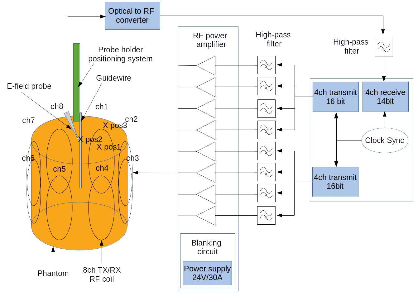
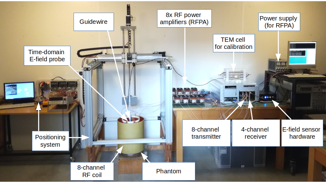
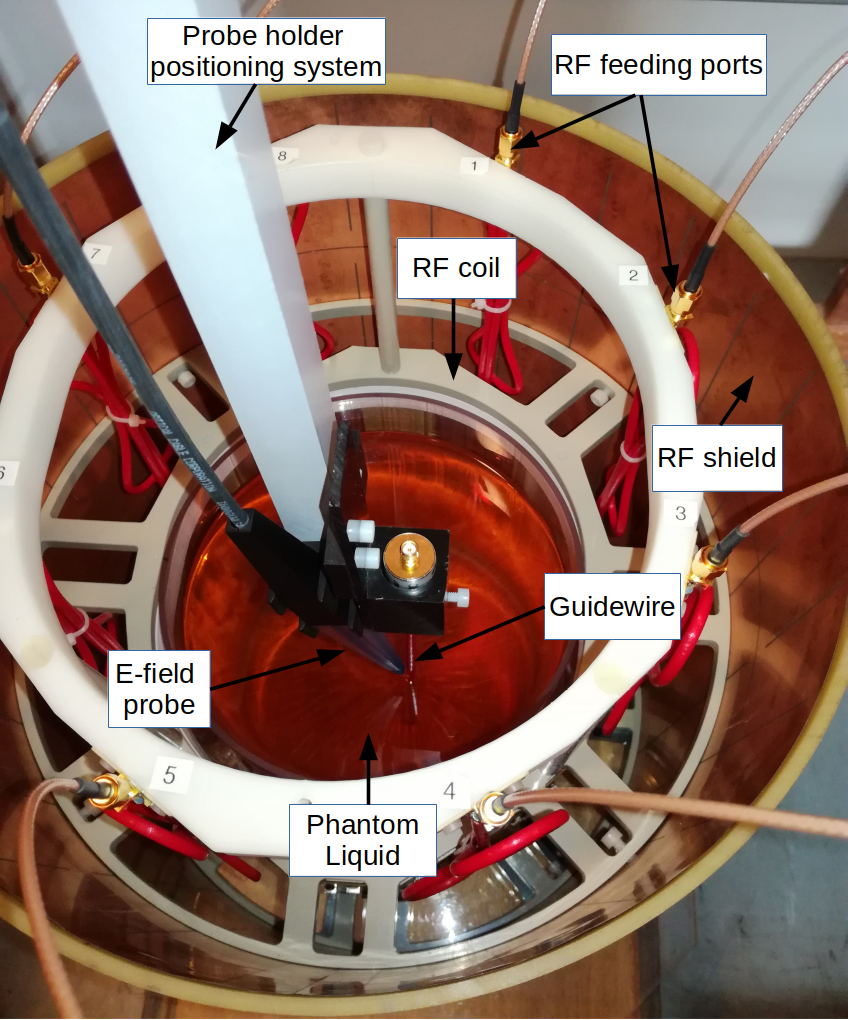
The home-built pTx medical implant safety testbed is depicted in Fig.1-3. It consists of 8-transmission and 4-reception channels using two 16-bit arbitrary waveform generators and a 14-bit digitizer (M4i.6622-x8 and M4i.4451-x8,Spectrum Instrumentation,Germany)(Fig.1). The maximum sampling rate of 625MS/s allows seamless transmission from 64-128MHz. For 297MHz a sampling frequency of 400MHz was used together with a high-pass filter (SHP-300+,Mini-Circuits,USA) to suppress aliasing. Eight 20W RF power amplifiers (ZHL-20W-13SWX+,Mini-Circuits,USA) are driven by a 24V/30A power supply with a customized blanking circuit. For precise positioning a 3D open-source positioning system was constructed7-8. An 8-channel pTx head coil9 was loaded with a cylindrical phantom (diameter=20cm, 44.1%polyvinylpyrrolidone, 55.1%water(deionized), 0.8%NaCl, ε=49.2 and σ=0.47S/m at 297MHz). A guidewire substitute was used to demonstrate mode dependent RF E-field induction and their mitigation by means of pTx pulses. Three locations inside the phantom were measured (pos1-3,Fig.1). For the geometry used, the tip SAR depends quadratically on the induced current close to the tip. Minimizing this current therefore reduces RF-induced heating at the tip. The electrically conductive guidewire forces Etan≈0 (incident + scattered field) in close vicinity to the wire, allowing to estimate the induced current based on a one-dimensional E-field probe perpendicular to the wire. For the present results we used a time-domain E-field sensor (E1TDSxSNI,Speag,Switzerland) positioned outside the phantom liquid (Fig.1&Fig.3).
At each measurement position an 8-dimensional (8-channel) complex valued vector $$$\overrightarrow{S}_{TDS},\overrightarrow{S}_{TDS}\in C$$$ was determined from the sensor signal by subsequent transmission of 8 voltage vectors $$$\overrightarrow{u_{t}}(i),\overrightarrow{u_{t}}\in C$$$ with the same phase and nonzero amplitude at channel j for j=i.
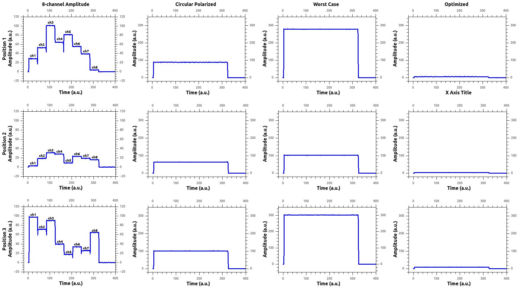
We then investigated three excitation scenarios, characterized by the transmitted voltage vectors $$$\overrightarrow{u_{t}'}$$$ with global forward power:
$$P_0=\overrightarrow{u_{t}}\cdot\overrightarrow{u_{t}}/8/Z_0, Z_0=50Ω$$
(i) Circular polarized (CP) mode: $$$\overrightarrow{u_{t}'}=\overrightarrow{u_{CP}}$$$, i.e. equal amplitudes and 45° phase increment per channel normalized to P0.
(ii) Worst case mode: $$$\overrightarrow{u_{t}'}=\overrightarrow{u_{WC}}$$$, i.e. phases are set for coherent superposition and voltage amplitudes are set according to the measured E-field sensor signals $$$\overrightarrow{S}_{TDS}$$$.
(iii) Optimized mode: Assuming normalization of $$$\overrightarrow{u_{CP}}$$$ and $$$\overrightarrow{u_{WC}}$$$:
$$\hat{u}_{CP}=\frac{\overrightarrow{u}_{CP}}{||\overrightarrow{u}_{CP}||}, \hat{u}_{WC}=\frac{\overrightarrow{u}_{WC}}{||\overrightarrow{u}_{WC}||}$$
$$\Rightarrow\hat{u}_{CP}\cdot\hat{u}_{CP}=\hat{u}_{WC}\cdot\hat{u}_{WC}=1$$
Projecting $$$\hat{u_t}'$$$ onto the orthogonal subspace minimizes the E-field10:
$$\hat{u}_{t}'=\hat{u}_{Opt}=\hat{u}_{CP}-\hat{u}_{WC}\cdot(\hat{u}_{WC}\cdot\hat{u}_{CP})$$
$$$\hat{u_t}'$$$ can subsequently be scaled to the desired forward power P0.
The 'worst case' mode generates the highest and the optimized mode the lowest E-fields at the probe position on the wire.
Results
Transmission and reception of the pTx system works reliably, the positioning system allows for precise positioning in the submillimetre range and the RF coil showed sufficiently good transmission SXX<-15dB and decoupling SXY<-12dB properties. Fig.4 displays the results of the RF induced E-field measurements. At pos1, which is slightly off-center, the strongest contributions in induced E-fields are from ch3-ch5, whereas at pos3 the strongest contributions are found by ch1-ch3 as expected. Pos2, which is approximately in the center of the RF coil, has lower induced E-field values confirming previous findings11. The worst-case E-fields resulted in a 3x times higher E-field compared to the CP mode. Minimizing the E-field vector by pTx, reduces the E-field >30-fold as compared to the worst case and >10-fold as compared to CP mode.Discussion and Conclusion
A parallel transmission implant safety
testbed was developed, that allows to investigate manifold MR safety
related scenarios. The testbed can be used in and outside the MR
scanner, which allows to investigate various sensor configurations.
With the current architecture, the number
of transmission/reception channels can be easily extended to 32.
The testbed can be used to investigate sensor-feedback
methods, perform validation measurements of MR based current detection methods
and investigate the MR safety of a variety of implants at 1.5T-7T.Acknowledgements
This work was funded by the EMPIR grant 17IND01 MIMAS. The EMPIR initiative is co-funded by the European Union’s Horizon 2020 research and innovation programme and the EMPIR Participating States.References
1 American Society for Testing Materials (ASTM). Standard Test Method for Measurement of Radio Frequency Induced Heating On or Near Passive Implants During Magnetic Resonance Imaging. ASTM International, 2011 2ISO/IEC TS10974, Assessment of the safety of magnetic resonance imaging for patients with an active implantable medical device, International Organization for Standardization, 2018
3 Van den Bosch MR, et al., New method to monitor RF safety in MRI-guided interventions based on RF induced image artefacts, Med Phys, 2010, 37:814-821
4 Griffin GH, et al., Safely assessing radiofrequency heating potential of conductive devices using image-based current measurements, MRM, 2015, 73:427-441
5 Eryaman Y, et al., A simple geometric analysis method for measuring and mitigating RF induced currents on Deep Brain Stimulation leads by multichannel transmission/reception, Neuroimage, 2019, 184:658-68
6 Weidemann G, Reduction of the E-field at the tip of implanted wires generated by pTx coils using RF current measurements, Proc ISMRM, 2016, #2216
7 Han H, et al., Open Source 3D multipurpose measurement system with submillimetre fidelity and first application in magnetic resonance, Scientific reports, 2017, 7(1):13452
8 http://www.opensourceimaging.org/cosi-measure
9 Seifert F, et al., 7T 8-channel pTx head coil with high B1+ efficiency optimized for MRS, Proc ISMRM, 2016, #3545
10 Seifert F, et al., Q-matrix approach to control implant heating by transmit array coils, Proc ISMRM, 2015, #3212
11 Eryaman Y, et al., Reduction of implant RF heating through modification of transmit coil electric field, MRM, 2011, 65(5):1305-13
Figures