0727
Reconfigurable coil technology significantly reduces the SAR at the tips of bilateral deep brain simulation leads during MRI at 3T: A realistic case study of isolated leads and fully-implanted systems1Electrical and Electronics Engineering, Bilkent University, Ankara, Turkey, 2Radiology, Northwestern University, Chicago, IL, United States, 3Life Science Engineering, Institute of Medical Physics and Radiation Protection, Giessen, Germany, 4Neurosurgery, Albany Medical Center, Albany, NY, United States, 5Northwestern University, Chicago, IL, United States
Synopsis
We report simulation results of specific absorption rate (SAR) at tips of bilateral deep brain stimulation (DBS) implants using a recently introduced reconfigurable MRI coil technology which uses a mechanically rotating linearly polarized birdcage transmitter. Using patient-derived realistic models of DBS leads both in isolation (i.e., leads that are not yet connected to the pulse generator) and fully-implanted DBS systems with different implanted pulse generator (IPG) configurations (i.e., a single dual-channel IPG feeding both leads, or two single-channel IPGs feeding left and right leads separately), we show that the rotating coil technology significantly reduces the SAR simultaneously at left and right leads during MRI at 3T.
Introduction
MRI of patients with deep brain stimulation (DBS) implants is very useful, both for target verification and to assess the “connectomic” functional effects of the neuromodulation [1]. Unfortunately, the interaction of scanner RF fields with elongated DBS leads causes safety concerns that restrict MRI accessibility to these patients. Recent studies are mostly based on steering electric-field free regions in MR transmit coils through design of implant-friendly modes using parallel transmit (pTx)[2-8]. Rendering pTx strategy is however, complicated for ordinary applications in the clinic. Recently, we introduced a reconfigurable MRI technology with a rotating transmit coil, which offers an easy operational setup yet significant reduction in SAR near tips of unilateral DBS leads during MRI at 1.5 T [9,10]. Here we present, for the first time, the feasibility of using such reconfigurable coil technology for DBS imaging at 3T. This is the first study to assess the performance of field-steering based methods to simultaneously reduce the SAR at tips of bilateral DBS leads, to use patient-derived realistic models, and to consider both isolated leads and fully-implanted DBS systems with different configurations.Methods
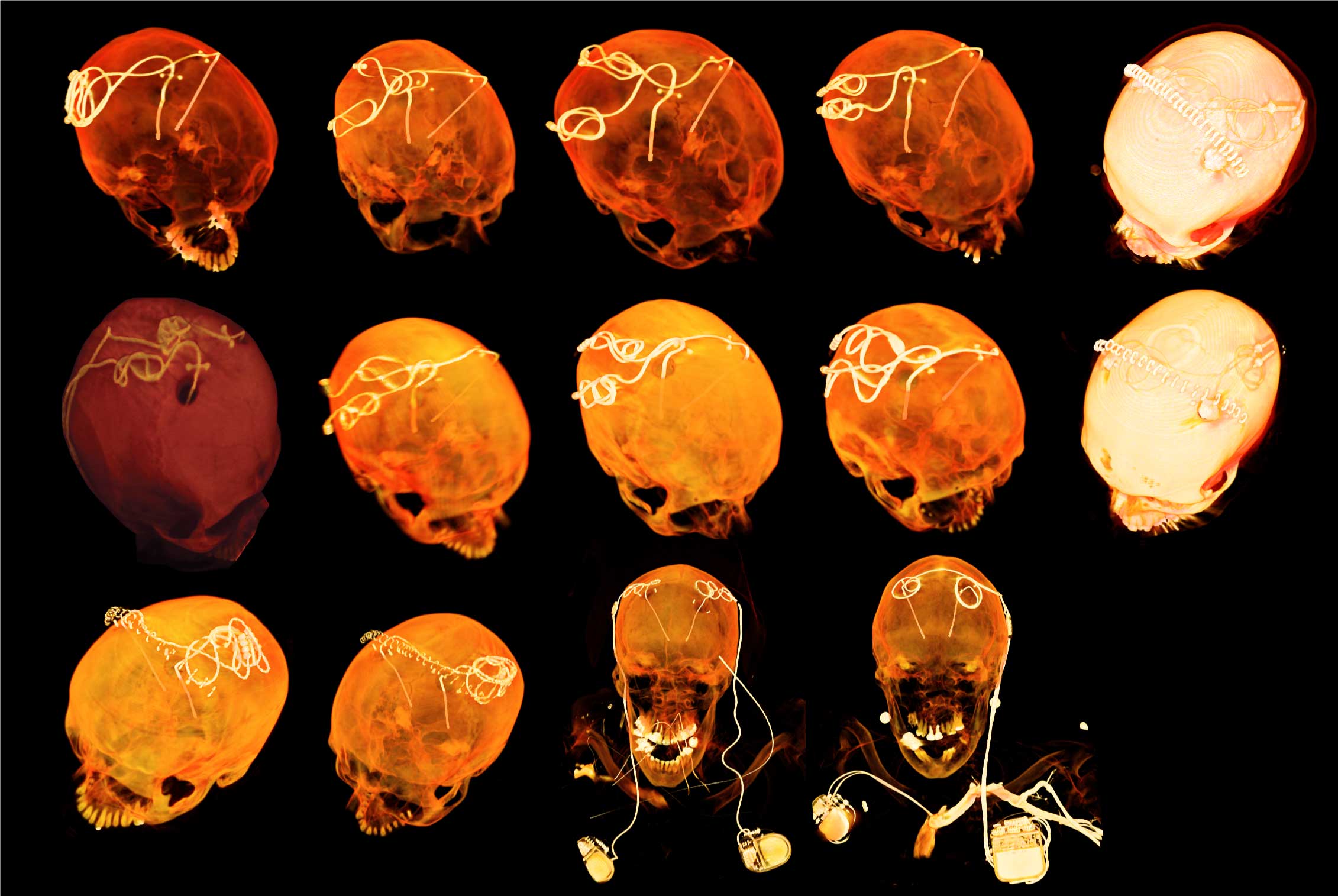
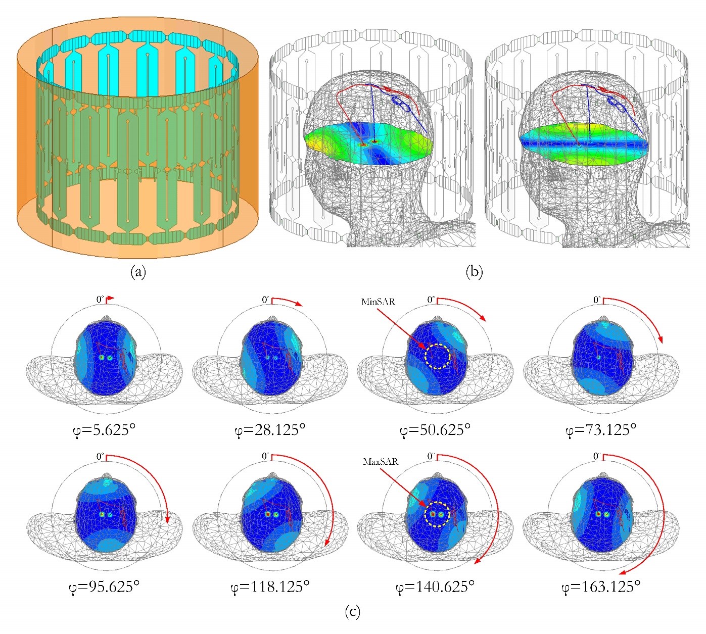
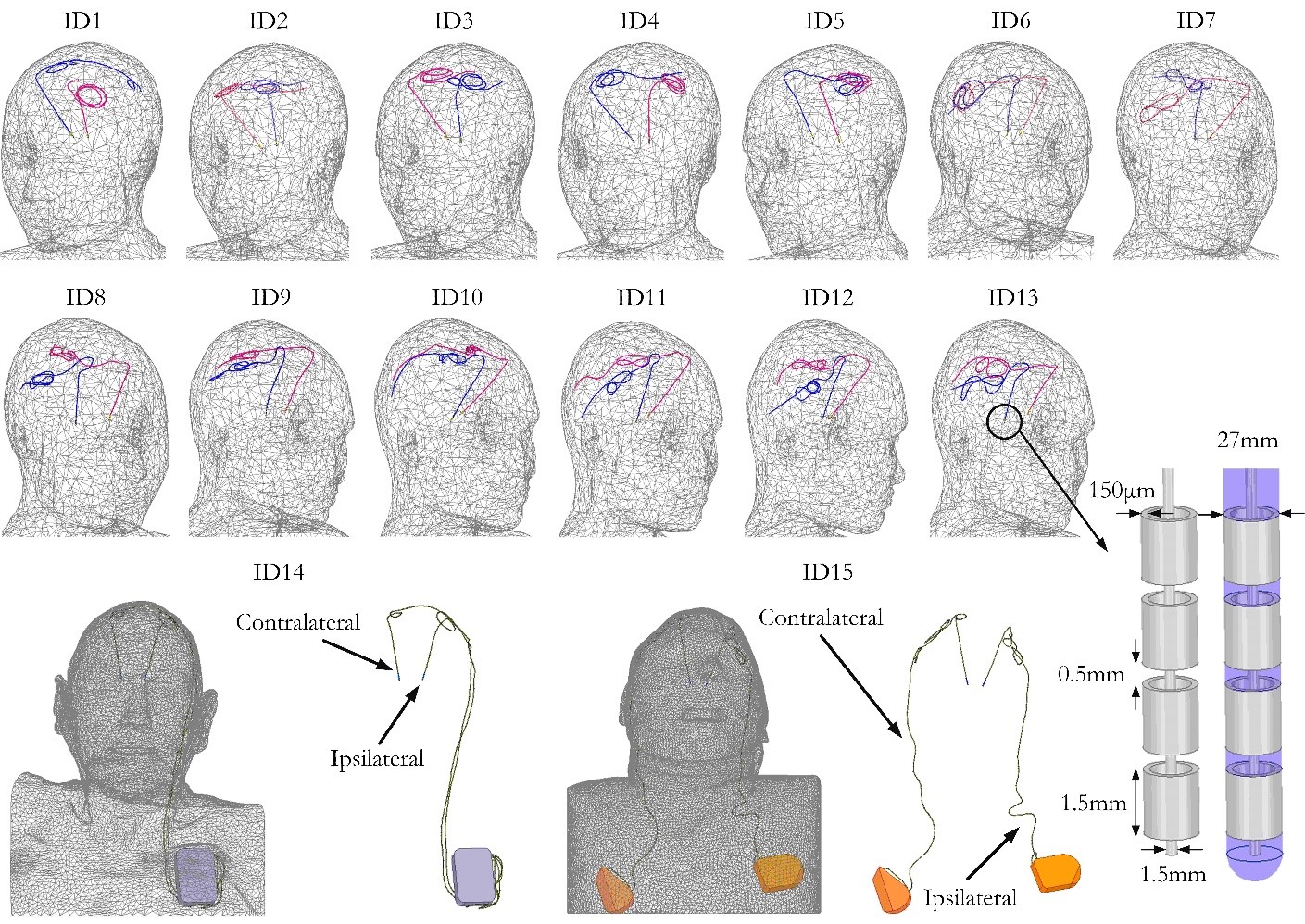
Fifteen (15) realistic lead models were constructed from postoperative CT images of patients operated for bilateral DBS. From these, 13 patients had bilateral isolated leads and two had a fully-implanted system with (a) a single dual-channel IPG feeding both left and right leads and (b) two single-channel IPGs feeding left and right leads separately (Fig.1). A total of 960 simulations were performed (15 patients×64 coil rotation angles) using the model of a 16-rungs linearly-polarized high-pass birdcage coil (Fig. 2(a)) currently under construction in our lab. Such a coil has a slab-like region of low electric field which can be steered by mechanically rotating the coil around the patient’s head to contain a substantial portion of the implant trajectory. Fig. 2(b) illustrates the coil’s electric field distribution on a central transverse plane for two different coil rotation angles. The 1g-averaged SAR distribution at 8 different coil rotation angles is shown in Fig. 2(c), demonstrating a substantial reduction in SAR at the implant’s tip when DBS leads are placed within the low electric field region of the coil. 1g-averaged SAR was calculated for each patient and at each coil rotating angle. For comparison, simulations were also performed for a CP coil with the input powers of the coils adjusted to produce a total head SAR of 3W/kg in all cases.Results
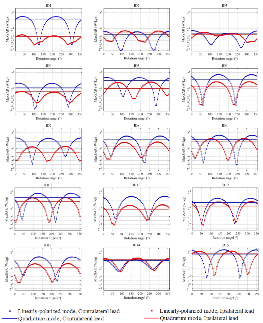
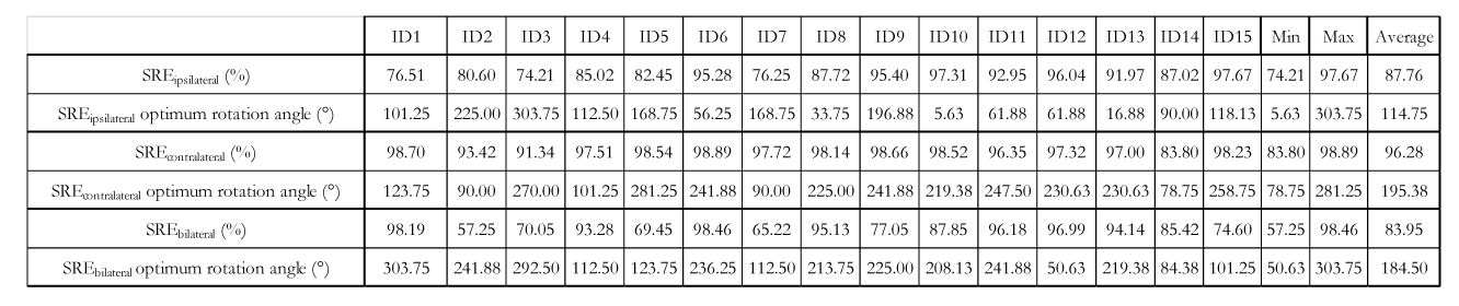
Fig. 4 gives the simulation results of the 1g-averaged SAR (1g-SAR) at the tips of ipsilateral and the contralateral leads as a function of coil rotation angle, with marked lines representing the rotating coil and solid lines representing the CP coil. To quantify the SAR-reduction performance of the reconfigurable coil system, we defined a metric called SAR-reduction efficiency (SRE) for each lead and at each rotation angle as:
SREn,i(φ)=100×(MaxSARCP, Patient n, Lead i-MaxSAR(φ)LP,Patient n, Lead i)/MaxSARCP, Patient n, Lead i
Where MaxSARCP, Patient n, Lead i is the maximum of 1gSAR at the tip of lead i (i=ipsilateral, contralateral) in patient n generated by the CP coil and MaxSAR(φ)LP,Patient n, Lead i is the maximum of 1gSAR at the tip of lead i in patient n generated by the LP coil positioned at angle φ.
SAR reduction efficiency for a single lead
When considering each lead alone, an average SRE of 88%±8% and 96%±4% was achieved for ipsilateral and contralateral leads respectively. As expected, the optimum coil rotation angle that minimized the SAR was different for ipsilateral and contralateral leads, emphasizing the importance of taking realistic trajectories into account [9-11]. In all cases however, there existed an intermediate rotation angle which simultaneously reduced the SAR at the tips of both left and right leads.
SAR reduction efficiency for bilateral leads
A bilateral SAR reduction metric can be defined as:
SREn,b(φ)=100×(MaxSARCP, Patient n-MaxSAR(φ)LP,Patient n)/MaxSARCP, Patient n
Where MaxSARCP/LP, Patient n is the maximum of 1gSAR in the tissue of patient n at whichever left of right lead that produces the higher SAR. When considering both leads together, an average bilateral SRE of 84% ±15% was achieved over all patients.
Conclusion
The reconfigurable coil system offers a simple setup and straightforward operation, yet significantly reduces the SAR at the tips of bilateral DBS implants with realistic trajectories, both in patients with isolated leads and in those with fully implanted systems.Acknowledgements
This work was supported by the NIH grant R00EB021320.References
[1] M. D. Fox, R. L. Buckner, H. Liu, M. M. Chakravarty, A. M. Lozano, and A. Pascual-Leone, "Resting-state networks link invasive and noninvasive brain stimulation across diverse psychiatric and neurological diseases," Proceedings of the National Academy of Sciences, vol. 111, no. 41, pp. E4367-E4375, 2014.
[2] C. McElcheran, L. Golestanirad, and S. Graham, "Reduced Heating of Implanted Electrical Conductors Using Parallel Radiofrequency Transmission," in Joint Annual Meeting of the International Society of Magnetic Resonace in Medicin (ISMRM), Milan, Italy, 2014.
[3] C. McElcheran et al., "Parallel Transmission for Heating Reduction in Realistic Deep Brain Stimulation Lead Trajectories," in Proc. Intl. Soc. Mag. Reson. Med. 25, 2017.
[4] C. McElcheran, L. Golestani-Rad, and S. Graham, "Heating Reduction in Unilateral And Bilateral Implanted Leads At 3T Using Parallel Radiofrequency Transmission in a Heterogeneous Head Model," in Proc. Intl. Soc. Mag. Reson. Med. 24, 2016.
[5] C. McElcheran, B. Yang, K. J. Anderson, L. Golenstani-Rad, and S. J. Graham, "Investigation of Parallel Radiofrequency Transmission for the Reduction of Heating in Long Conductive Leads in 3 Tesla Magnetic Resonance Imaging," PLoS One, vol. 10, no. 8, p. e0134379, 2015.
[6] C. E. McElcheran, B. Yang, K. J. Anderson, L. Golestanirad, and S. J. J. M. r. i. m. Graham, "Parallel radiofrequency transmission at 3 tesla to improve safety in bilateral implanted wires in a heterogeneous model," vol. 78, no. 6, pp. 2406-2415, 2017.
[7] Y. Eryaman, B. Akin, and E. Atalar, "Reduction of implant RF heating through modification of transmit coil electric field," Magnetic resonance in medicine, vol. 65, no. 5, pp. 1305-1313, 2011.
[8] Y. Eryaman et al., "Parallel transmit pulse design for patients with deep brain stimulation implants," Magnetic resonance in medicine, vol. 73, no. 5, pp. 1896-1903, 2014.
[9] L. Golestanirad et al., "Construction and modeling of a reconfigurable MRI coil for lowering SAR in patients with deep brain stimulation implants," Neuroimage, vol. 147, pp. 577-588, 2017.
[10] L. Golestanirad, B. Keil, L. M. Angelone, G. Bonmassar, A. Mareyam, and L. L. Wald, "Feasibility of using linearly polarized rotating birdcage transmitters and close‐fitting receive arrays in MRI to reduce SAR in the vicinity of deep brain simulation implants," Magnetic resonance in medicine, vol. 77, no. 4, pp. 1701-1712, 2017.
[11] L. Golestanirad, L. M. Angelone, M. I. Iacono, H. Katnani, L. L. Wald, and G. Bonmassar, "Local SAR near deep brain stimulation (DBS) electrodes at 64 MHz and 127 MHz: A simulation study of the effect of extracranial loops " Magnetic Resonance in Medicine vol. 78, no. 4, 2017.
[12] L. Golestanirad et al., "Changes in the specific absorption rate (SAR) of radiofrequency energy in patients with retained cardiac leads during MRI at 1.5 T and 3T," Magnetic resonance in medicine, 2018. [13] L. Golestanirad et al., "RF-induced heating in tissue near bilateral DBS implants during MRI at 1.5 T and 3T: The role of surgical lead management," Neuroimage, vol. 184, pp. 566-576, 2019.
Figures