0573
Fast transmit/receive switch for SWIFT imaging at 7T1Center for Magnetic Resonance Research, University of Minnesota, Minneapolis, MN, United States
Synopsis
Sweep imaging with Fourier transformation (SWIFT) can image extremely short-lived MRI signals such as cortical bone and lung. However, it requires fast transmit/receive (T/R) switching during the gapped RF excitation, which cannot be handled with standard clinical MRI hardware. A fast transmit/receive switch (switching time ≤ 400 ns) is developed for integration into an 8-channel in-bore T/R switch interface. These T/R switches are driven via repurposed Varian PIN drivers which are, in turn, triggered via an optical-to-TTL signal. This hardware enabled the acquisition of SWIFT images of the human head at 7T with an 8-channel transmit/receive degenerate birdcage coil.
Purpose
Sweep imaging with Fourier transformation (SWIFT) is a powerful technique to image extremely short-lived MRI signals such as cortical bone and lung [1]. However, it requires fast transmit/receive (T/R) switching during the gapped RF excitation, which cannot be handled with standard clinical MRI hardware. In this study, we developed a fast T/R switch for SWIFT (or ultra-short TE) imaging on a 7T MRI system.Methods
Four models of PIN diode were tested (MA4P7470F, MA4P7104F, MA4P1250NM, and MA4P504; MACOM, USA) in two competing circuit topologies and the switching speed of these circuits was compared. These PIN diodes were chosen both because they were readily available and were previously used successfully for T/R switching applications in our lab.
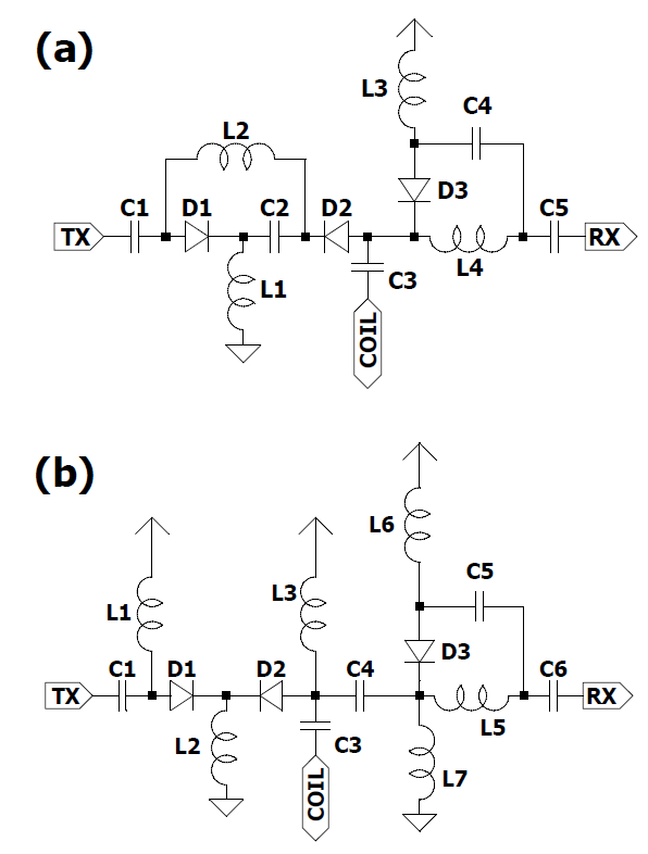
T/R switches were initially bench tested. The circuit topologies compared include a series (Fig 1a) and parallel circuit (Fig 1b). They were driven by an RFFE PIN diode driver (Varian, CA, USA). The driver was triggered by a pulse generator (8110A, Hewlett Packard, USA). An RF signal was injected into the circuit with a signal generator (SMY02, Rohde & Schwarz, Munich, Germany) and detected on an oscilloscope (DPO4104, Tektronix, USA). The time from TTL high signal to 90% of maximum RF was defined as the rise time and TTL low signal to 10% of maximum RF defined as the fall time. PIN diodes switch faster when driven with short pulses thus all measurements were made with long pulses to ensure worst case switching times were measured.
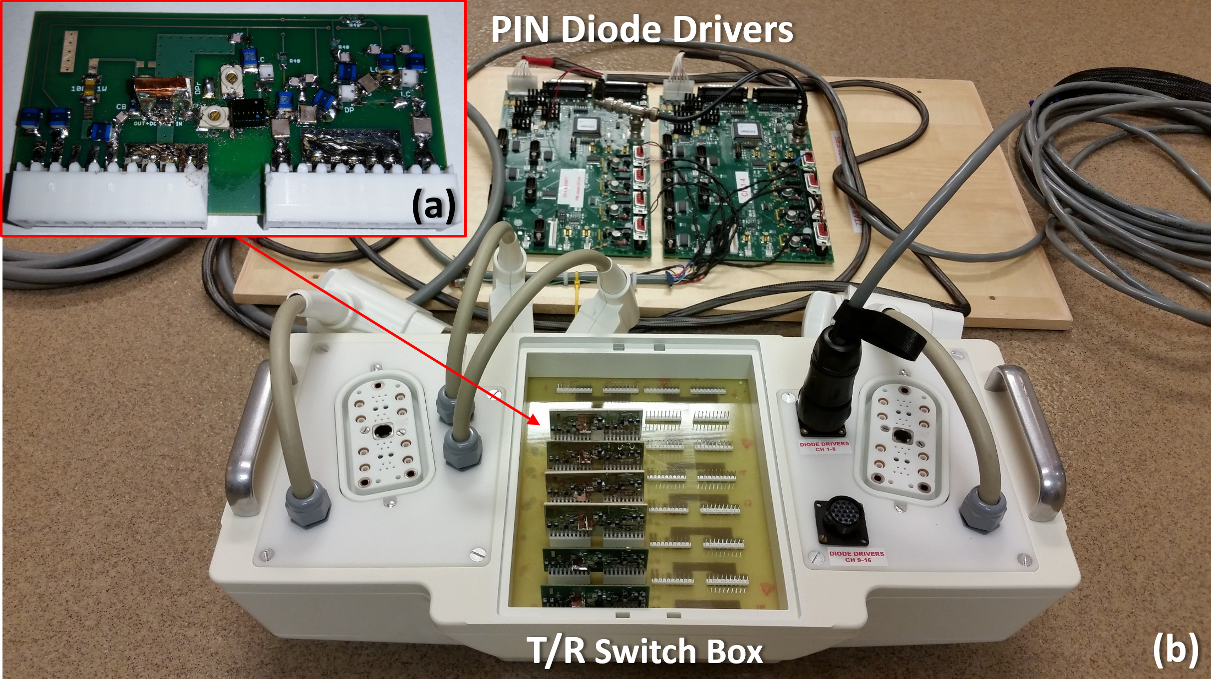
At the conclusion of the comparison, a fast T/R switch was fabricated (Fig 2a) which plugs into a 16-channel T/R switch box (Fig 2b) and fits precisely into the patient bed. PIN diode lines on 8 channels of this T/R switch box were driven via a pair of 4-channel RFFE PIN drivers (Fig 2b). Since the fastest controllable trigger of the Siemens console (10 μs) is ~10-fold slower than the desired switching speed, we developed a custom trigger device capable of 2.5 ns resolution and interfaced this with our PIN drivers.
Phantom and in vivo head images were acquired on a 7T MRI system (Siemens MAGNETOM, Germany) using a 8-channel degenerate birdcage coil for both excitation and reception. The coil was interfaced to the MRI system via the fast T/R switch interface which we developed. To achieve this, we supplied our own DC power, PIN diode driver signal, and TTL trigger.
Gapped pulse excitation was done with a flattened hyperbolic secant pulse (HS2) [2] having 50 kHz bandwidth and 32 gaps, each in a 20 μs segment (4 μs pulse and 16 μs gap). After the gapped pulse excitation, signal reception continued with 100% receiver duty cycle with the gradients ramping up to 192 kHz of bandwidth [3]. In image reconstruction, acquired radial k-space data were deconvolved with the HS2 excitation profile to remove the quadratic phase and then reconstructed to an image by gridding onto a 3D Cartesian k-space followed by FFT.
Results and Discussion
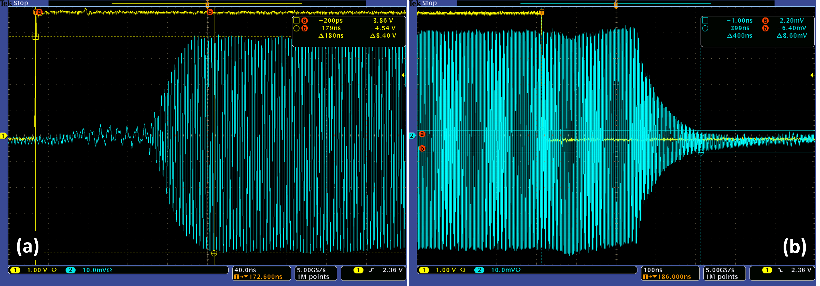
The circuit with series driven PIN diodes (Fig 1a) had rise times >18% slower and fall times >59% slower than parallel driven PIN diodes (Fig 1b). Switching speeds of the various diodes compared are shown in Table 1. The fastest PIN diode tested was the MA4P504 in MELF (1072T) packaging. This diode became the basis for the fast T/R switch used in this work (Fig 2). The switching speed of the resulting T/R switch is shown in Figure 3. The T/R switch achieves TX-RX isolation of 34.9 dB in receive mode and 44.8 dB in transmit mode.
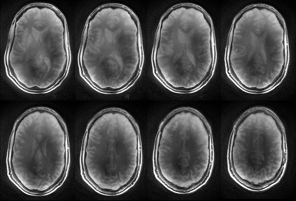
Fast T/R switching was tested with in vivo SWIFT imaging at 7T which required switching to transmit then back to receive during a 20 μs period. The reconstructed image did not show any clear artifacts related to T/R switching (Fig.4).
Conclusion and Future Work
In this work we developed fast T/R switches (switching speeds ≤ 400 ns) compatible with SWIFT and other ultra-short TE imaging at 7T. These modular T/R switches have been used to demonstrate multichannel SWIFT imaging.
The next goal is to acquire SWIFT images using a 16-channel coil and T/R switch interface. One limitation of this work was our dependence upon the ability to rapidly blank/unblank the RFPA to prevent noise from swamping the receivers. To address this concern, the fast T/R switches described herein are being modified to achieve higher TX-RX isolation on receive (~ 48 dB), thus negating the requirement for rapid RFPA blank/unblank. This is an important step towards integration with current commercial MRI systems.
Acknowledgements
This work was funded by NIH-NIBIB P41 EB015894, NIH-NIBIB S10 RR026783, and the WM KECK foundation.References
[1] Idiyatullin, D., et al., Fast and quiet MRI using a swept radiofrequency. J Magn Reson, 2006. 181(2): p. 342-9.
[2] Garwood, M. and L. DelaBarre, The return of the frequency sweep: designing adiabatic pulses for contemporary NMR. J Magn Reson, 2001. 153(2): p. 155-77.
[3] Kobayashi, N., et al., 3D Cine Magnetic Resonance Imaging of Rat Lung ARDS using Gradient-modulated SWIFT with Retrospective Respiratory Gating. Proc SPIE Int Soc Opt Eng, 2015. 9417.
Figures