0565
Flexible multi-turn multi-gap coaxial RF coils (MTMG-CCs): design concept and bench validation1IR4M (Imagerie par Résonance Magnétique et Multi-Modalités), UMR 8081, Université Paris-Sud/CNRS, Université Paris-Saclay, Orsay, France, 2Division MR Physics, Center for Medical Physics and Biomedical Engineering, Medical University of Vienna, Vienna, Austria, 3Université de Lorraine, Inserm, IADI, Nancy, France
Synopsis
The design of flexible coaxial coils (CCs) based on the single-turn single-gap concept is extended by multiple turns and multiple gaps (MTMG-CCs) to achieve a larger range of coil diameters for a given resonance frequency. An equivalent circuit for MTMG-CCs is presented and the resonance condition is solved numerically for coils with diameters up to 20 cm, 1-3 turns, and 1-3 gaps. For validation of the calculations, 27 coils with 6/9/12 cm diameters, 1-3 turns, and 1-3 gaps were built and characterized on the bench.
Purpose
In RF coil array development, auto-resonant structures such as transmission line resonators (TLRs)1,2 implemented using coaxial cables3,4 exploit the advantages of flexibility, close-fitting design, light weight, and robustness to coil overlap variations3. As previously reported3,5, with a single turn of coaxial cable and a single gap in outer and inner conductor, the coaxial coil diameter is dictated by the desired resonance frequency (f0) and properties of the coaxial cable used, such as the outer conductor diameter (d1), the characteristic impedance (Z0), and the relative permittivity (εr) of the dielectric. Therefore, the coil diameter cannot be chosen freely, and the resulting coil size is not necessarily the optimum for a given clinical application. In this work – based on multi-turn multi-gap (MTMG) transmission line resonators6 – an extended design of coaxial coils with more than one gap and/or cable turn (MTMG-CCs) is proposed with the goal to increase the degrees of freedom in coaxial coil design. The design concept is studied by numerical simulation and bench measurements using 27 different MTMG-CC configurations made of one coaxial cable type.Methods
Design concept and resonance frequency calculation:
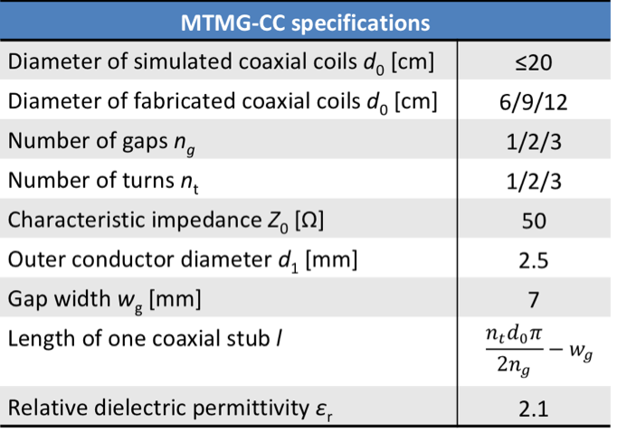
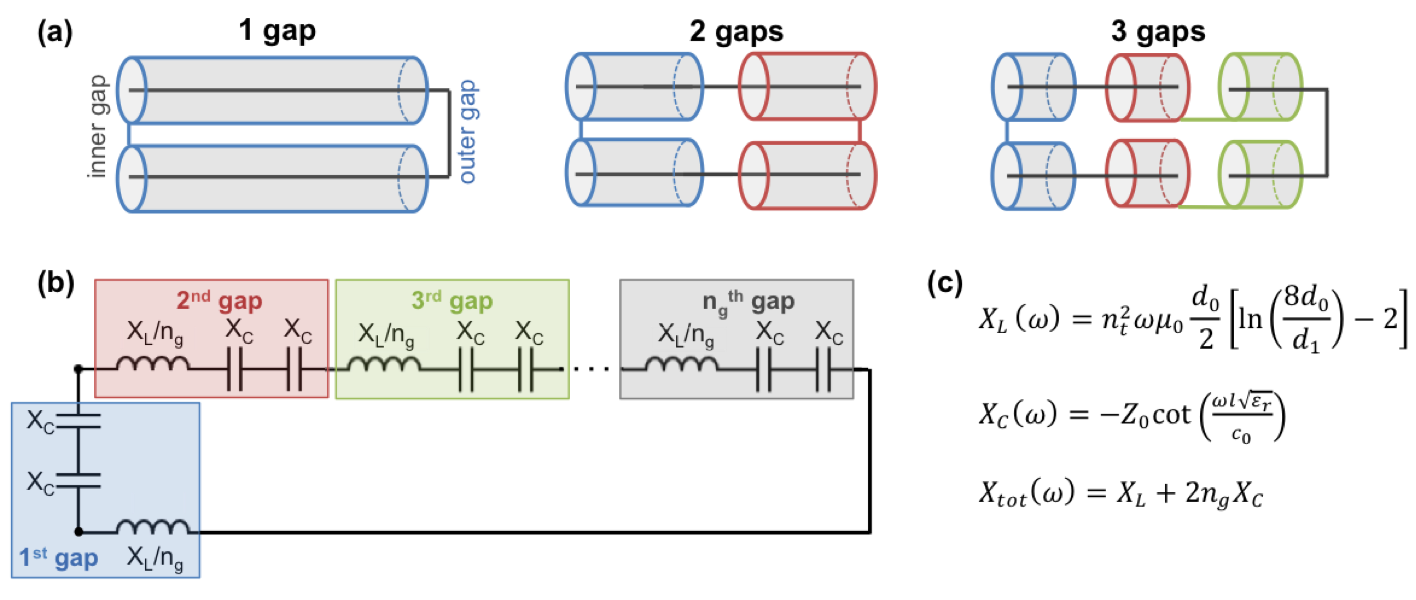
Tab.1 lists the design properties of all investigated MTMG-CCs. Example layouts of coaxial coils with either one, two or three gaps are schematically drawn in Fig.1a. The equivalent circuit for MTMG-CCs is presented in Fig.1b. The total inductive reactance XL is approximated as the inductance of a conductive loop of the same diameter and thickness as the outer shield of the coaxial coil, which is proportional to the squared number of turns (nt) of the coaxial cable. The total capacitive reactance is obtained assuming that the coil consists of 2ng (twice the number of gaps) lossless open-ended coaxial stubs in series and using the classical capacitive reactance formula of a stub. The corresponding equations are given in Fig.1c. At resonance, the total reactance equals zero, thus the resonance condition for an MTMG-CC can be derived. From this, considering the specific cable type used for coil construction (εr=2.1, d1=2.5mm, Z0=50Ω), the resonance frequency was calculated using MATLAB 2017b (The Mathworks, Inc., Natick, USA) for various coaxial coil diameters (d0≤20cm) and MTMG-CC configurations with ng=1-3 and nt=1-3.
Bench measurements:
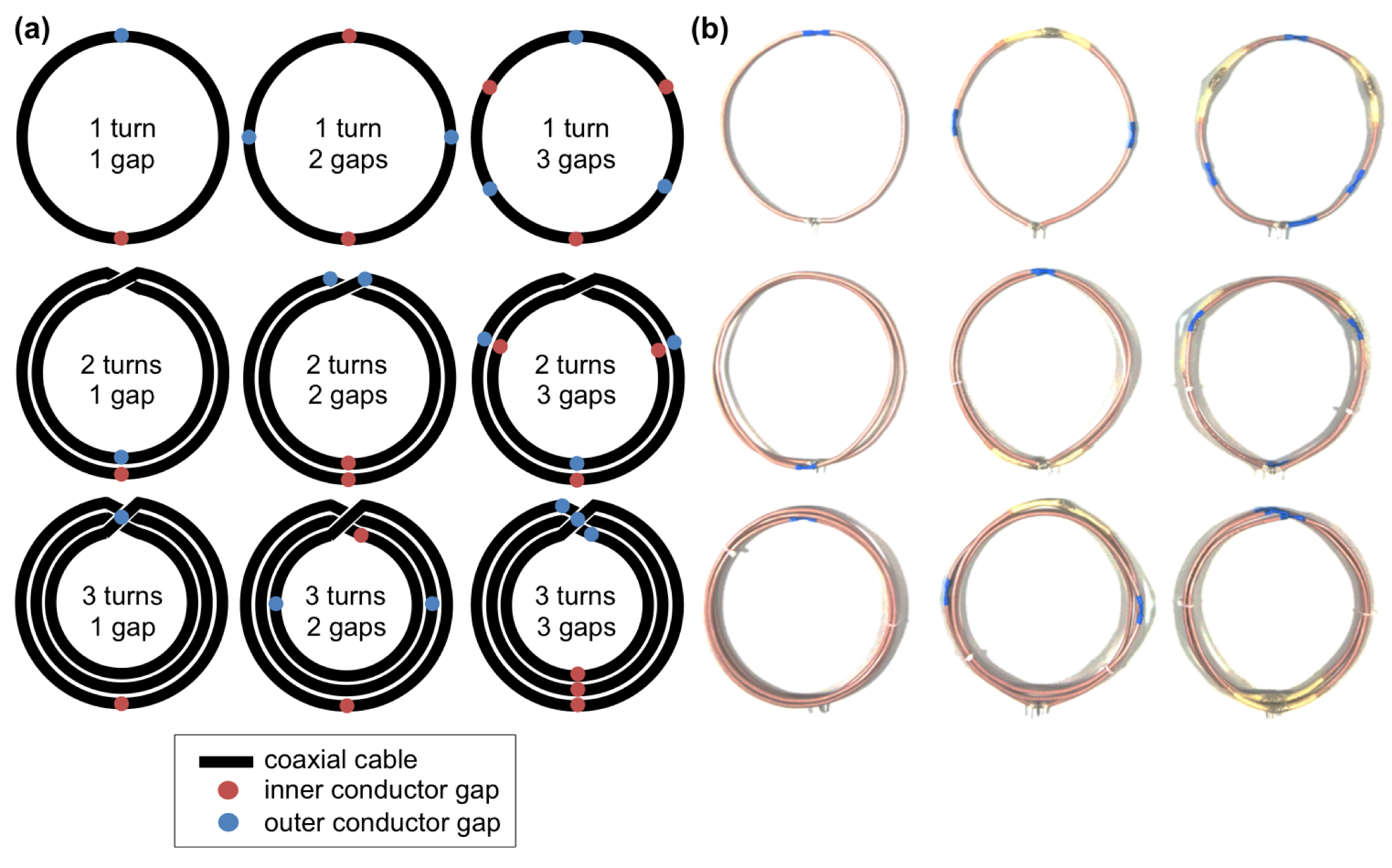
A total of 27 MTMG-CCs with diameters of 6, 9 and 12 cm, ng=1-3, and nt=1-3, yielding 9 different coil configurations per diameter (Fig. 2a), were fabricated from non-magnetic coaxial cable (K_02252_D-08, Huber+Suhner, Pfäffikon, Switzerland) with gaps of 7mm width (Tab.1). The set of 9 MTMG-CCs with d0=12 cm is depicted in Fig.2b. At a constant distance from the MTMG-CC, a decoupled double-loop probe7 was used to evaluate the coil’s quality factor Q, and the resonance frequency (f0) for the unloaded and loaded coil setup. A torso-shaped phantom (≈57x38x23cm3) with tissue equivalent properties (σ=0.60S/m, εr=62) was used as a load.
Results and discussion
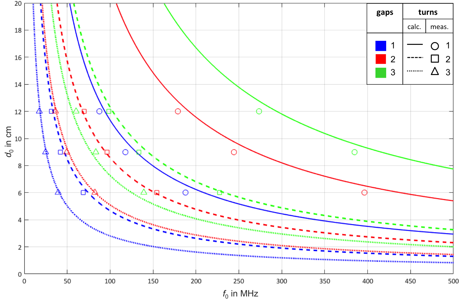
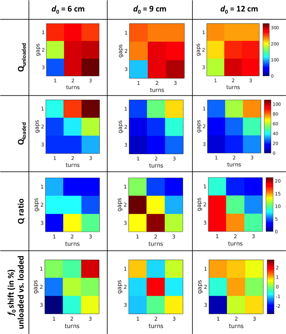
Calculation results for the 27 investigated MTMG-CC configurations presented in Fig. 3 demonstrate that – for a fixed coil diameter – the resonance frequency increases with the number of gaps and decreases with the number of turns. At a given resonance frequency, compared to a single-turn single-gap coaxial coil, using multiple turns allows for smaller coil diameters, whereas adding gaps allows for larger coil diameters. Bench measurement results including Q-factors (unloaded and loaded), Q-ratios and the f0 shift between loaded and unloaded case are summarized in Fig.4. All Q-ratios are superior to 2, indicating coil operation in a sample noise dominated regime. A drop in Qunloaded can be observed as the resonance frequency increases (high ng, low nt, small coil diameter), which could be explained by other loss mechanisms (e.g. dielectric losses or radiation losses) becoming dominant over resistive losses at high frequencies. The fabricated MTMG-CCs have resonance frequencies ranging from 18 to 632 MHz. The maximum measured f0 shift due to loading is less than 3%. Simulated f0 values for the unloaded setup deviate up to ±11.3% from measured results (Fig.3). In practice, an additional capacitor or inductor at the coil port (between the inner conductors) can be used for fine-tuning.Conclusion
In this work, we present a design scheme and equivalent circuit for multi-turn multi-gap coaxial RF coils, exhibiting outstanding mechanical flexibility. Predicted resonance frequencies from numerical simulations sufficiently match measured results for reliable MTMG-CC design. The use of multiple gaps and/or turns offers more degrees of freedom compared to a single-turn single-gap coaxial coil whilst maintaining mechanical flexibility and thus enlarges the range of clinical applications of coaxial coils.Acknowledgements
This project was funded by the Austrian/French FWF/ANR grant, Nr. I-3618, “BRACOIL“, and Austrian/French OeAD WTZ grant FR 03/2018.References
1. Gonord P, et al. Multigap parallel-plate bracelet resonator frequency determination and applications. Rev Sci Instrum. 1994;65:3363–3366.
2. Kriegl R, et al. Novel inductive decoupling technique for flexible transceiver arrays of monolithic transmission line resonators. Magn Reson Med. 2015;73(4):1669–1681.
3. Zhang B, Sodickson D K, Cloos M A. A high-impedance detector-array glove for magnetic resonance imaging of the hand. Nat Biomed Eng. 2018;2(8):570–577.
4. Yang X, et al. Coaxial cable magnetic resonance image (MRI) coil. US patent US9678180B2; 2017.
5. Laistler E, Moser E. Handy magnetic resonance coils. Nat Biomed Eng. 2018;2:557–558.
6. Frass-Kriegl R, et al. Multi-turn multi-gap transmission line resonators – Concept, design and first implementation at 4.7T and 7T. J Magn Reson. 2016;273:65–72.
7. Darrasse L, Kassab G. Quick measurement of NMR-coil sensitivity with a dual-loop probe. Rev Sci Instrum. 1993;64(7):1841–1844.
Figures