0564
Approaching the ultimate intrinsic coil performance for 7T body imaging with high-density parallel transmit/receive arrays1Image Sciences Institute, University Medical Center Utrecht, Utrecht, Netherlands, 2Radiology, WaveTronica B.V., Utrecht, Netherlands, 3Avans Hogeschool Den Bosch, Den Bosch, Netherlands, 4New York University School of Medicine, New York, NY, United States, 5Biomedical Image Processing, Eindhoven University of Technology, Eindhoven, Netherlands
Synopsis
In order to calculate
Introduction
Body imaging at 7T is typically performed with local transceive arrays with up to 16 transmit channels. Recent work showed that it can be beneficial scale up to 32 transmit channels1–3. However, it is not yet known how well these designs approach the theoretical optimum. The upper-bound of coil performance is given by the ultimate intrinsic signal-to-noise ratio4–6 (uiSNR, receive) and the ultimate intrinsic SAR efficiency (uiSAReff, transmit). In this work, we evaluate the performance of high density transceive arrays for prostate imaging at 7T. First, we determined the uiSNR and uiSAReff in a realistic human model. Subsequently, four transceive arrays are simulated on the same body model and benchmarked against the ultimate intrinsic coil performance. Finally, a 32 channel RF amplifier setup was used to garner initial experimental tests with a 24 channel transceive coil on this system.Methods
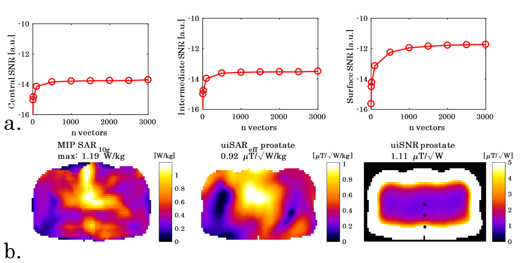
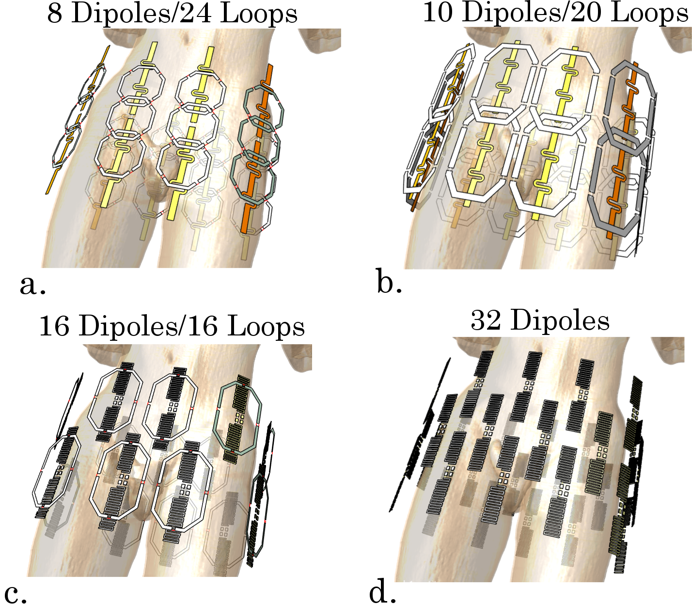
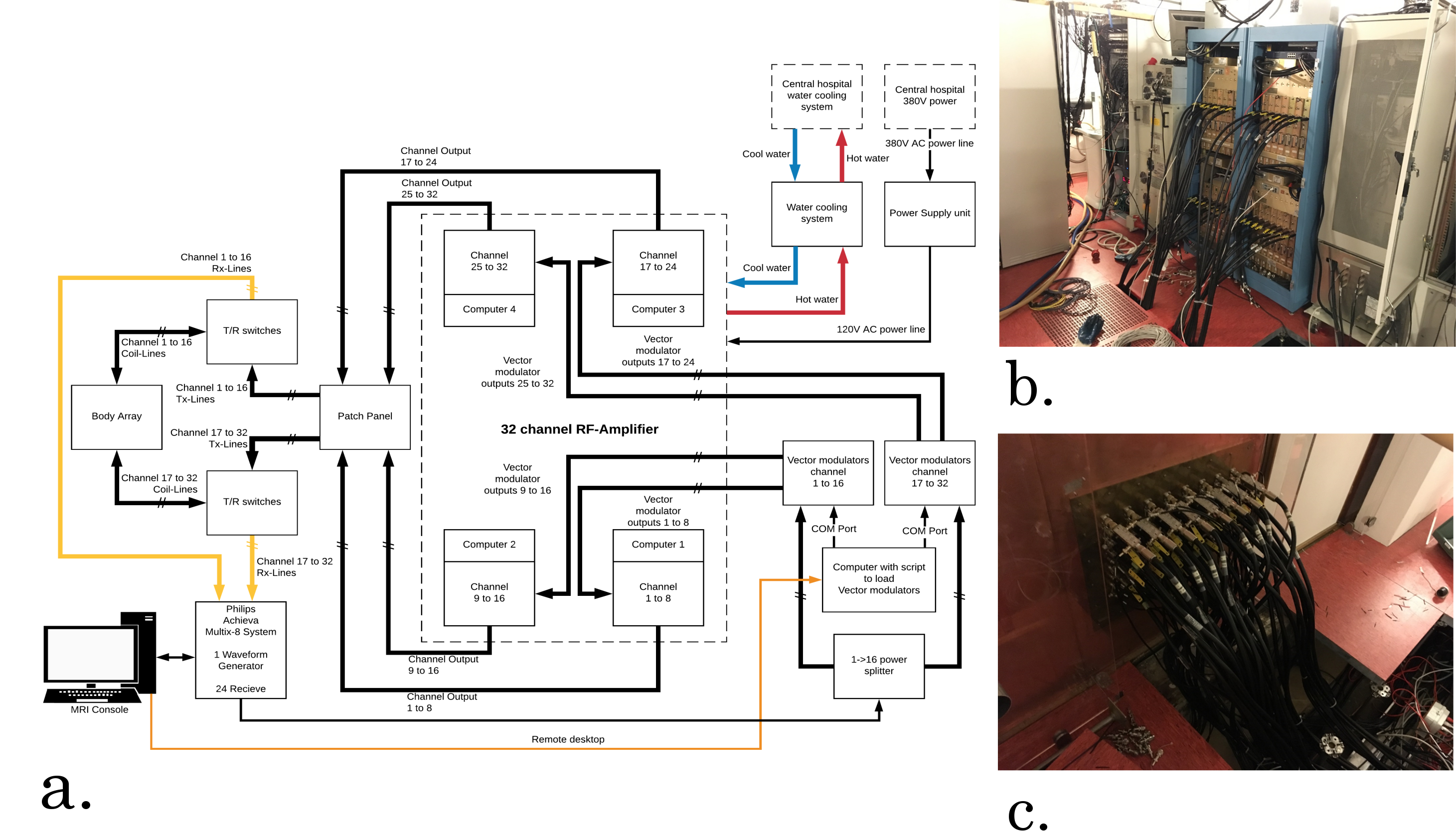
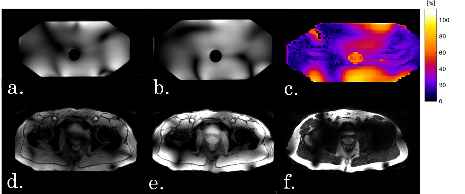
Online available tools provided by Guerin et al6 were used to obtain a full basis of E- and H-fields in a cropped section of the human pelvis (Duke, 5x5x5 mm3, 30x40x30 cm3, using 3000 randomly excited combinations of dipoles). uiSNR (including receive sensitivity, but not B0) was calculated as a root-sum-of-squares combination of the receive fields and the noise covariance7 The uiSAReff was approximated by a weighted sum of basis vectors that minimizes global SAR levels4. SAReff was then calculated as the average B1+ in the prostate, normalized by local peak SAR in the volume. To check convergence of the full basis, uiSNR was evaluated for different numbers of basis vectors (figure 1). Four coil arrays were simulated in a prostate scan configuration (Duke, virtual family8) using a Finite Difference Time Domain (FDTD) method (Sim4life, Zurich Med Tech, Zurich, Switzerland). All coils were based on designs from literature, comprising combinations of loop and dipole elements9–12 (Figure 2). Using the generalized virtual observation points framework13, optimal SAReff was calculated in the prostate. Average SNR in the prostate was evaluated with the root-sum-of-squares method7. As a figure of merit, the average of SAR efficiency and SNR, both expressed with respect to the uiSNR and uiSAReff, was calculated. (Figure of Merit=(SAReff,relative+SNRrelative)/2). To obtain insight in potential acceleration performance, the cumulative sum of singular values of receive fields in a transverse slice through the prostate was calculated14. Worst-case SAR, considering equal and unitary input power to all channels, was calculated for each array15. A 32x1kW channel RF amplifier (Analogic Corporation, Peabody, USA) was integrated with the Philips Achieva 7T system (Philips Healthcare, Best, The Netherlands, Amplifier installation: WaveTronica B.V., Utrecht, The Netherlands). Two 16 channel vector modulators were used to control amplitude and phase of each amplifier output. The RF amplifiers were connected to the scanner system using 32 low-loss coaxial cables, going into two custom-built transmit/receive-switches. After obtaining IRB approval, a phantom (ethyleneglycol, ε=34, 0.4 S/m) and a male volunteer (age 39, BMI 24.6) were scanned using 24 channels of a 30 channel loop-dipole array (figure 2b).Results
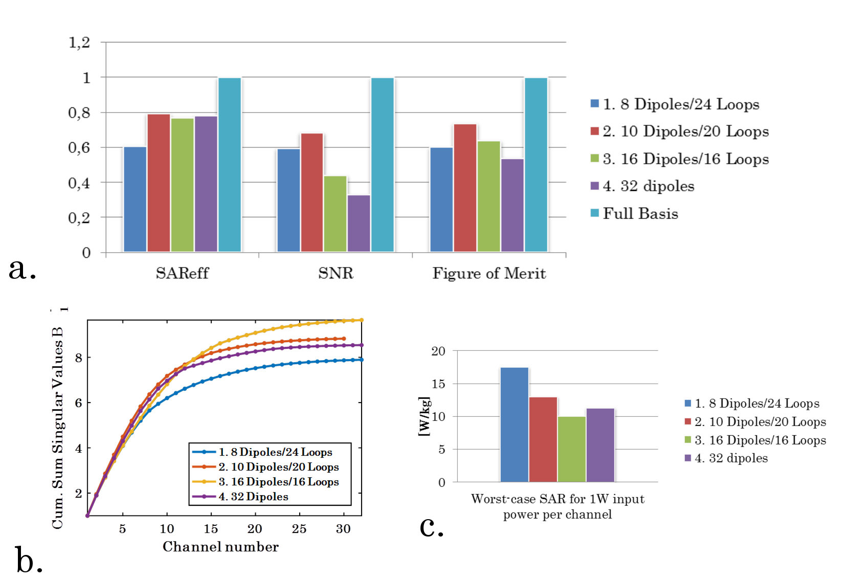
Figure 1 shows uiSNR and uiSAReff in the prostate for Duke. SAR efficiency in the prostate is 0.92 μT/√W/kg, while uiSNR is 1.11 μT/√W. Figure 2 shows the different array setups that were compared in this work, while figure 3 summarizes the results of this comparison. The best SAR efficiency is obtained with a 10 Dipole/20 Loop array (79% of uiSAReff), this array also has the best SNR performance (68% of uiSNR, 73% of figure of merit). Setups which include dipoles distributed in the z-direction (staggered dipoles) have lower SNR in the prostate (44% and 33% of uiSNR). In terms of acceleration performance and minimum worst-case SAR values, the 16 Dipole/16 Loop array performs best. Figure 4 shows a schematic overview of the RF-amplifiers, while figure 5 shows initial results obtained in a phantom and a volunteer.Discussion
For the first time, uiSNR and uiSAReff were calculated in a realistic human model for a prostate imaging setup. It is demonstrated that by using 32 transceive channels, 79% of the uiSAReff and 68% of uiSNR can be obtained in the prostate. The best performing array in this comparison uses 10 Dipoles and 20 loops, which outperforms the other arrays in this comparison especially in terms of SNR. Planned future work might improve the uiSNR and uiSAReff calculations by simulating Duke at a higher resolution and by optimizing SAReff while considering peak SAR levels in the optimization. Practical tests with the 32-channel amplifier system will be continued, with the aim of doing a comparison of the simulated arrays with the full number of transmit channels (30 or 32 instead of the current 24).Acknowledgements
The project described was supported by a grant from Dutch Technology Foundation STW, grant number 13783.
The project described was supported by an equipment grant from NYU Langone Medical Center and its Center of Biomedical Imaging.
The authors would like to thank Daniel Sodickson and Martijn Cloos from New York University Medical Center, for transferring the 32 channel RF amplifier to University Medical Center Utrecht.
References
1. Ertürk MA, Wu X, Adriany G, Lagore RL, Ugurbil K, Metzger GJ. An improved 32-channel loop-dipole transceiver array design for body imaging at 7.0 Tesla: Simulation study. Proc 26th Annu Meet ISMRM, Paris, Fr. 2018.
2. Orzada S, Bitz AK, Gratz M, et al. A 32-channel transmit system add-on for 7 Tesla body imaging. Proc 25th Annu Meet ISMRM, Honolulu, Hawaii. 2017:1219.
3. Steensma BR, Teixeira J, Voogt IJ, et al. Towards massively parallel multi-transmit for body imaging at 7T. Proc 25th Annu Meet ISMRM, Honolulu, Hawaii. 2017:1218.
4. Lattanzi R, Sodickson DK, Grant AK, Zhu Y. Electrodynamic constraints on homogeneity and radiofrequency power deposition in multiple coil excitations. Magn Reson Med. 2009;61(2):315-334. doi:10.1002/mrm.21782.
5. Lattanzi R, Sodickson DK. Ideal current patterns yielding optimal signal-to-noise ratio and specific absorption rate in magnetic resonance imaging: Computational methods and physical insights. Magn Reson Med. 2012;68(1):286-304. doi:10.1002/mrm.23198.
6. Guérin B, Villena JF, Polimeridis AG, et al. The ultimate signal-to-noise ratio in realistic body models. Magn Reson Med. 2017;78(5):1969-1980. doi:10.1002/mrm.26564.
7. Roemer PB, Edelstein WA, Hayes CE, Souza SP, Mueller OM. The NMR phased array. Magn Reson Med. 1990;16(2):192-225. doi:10.1002/mrm.1910160203.
8. Kuster AC and WK and EGH and KH and MZ and EN and WR and RJ and WB and JC and BK and PS and H-PH and J. The Virtual Family—development of surface-based anatomical models of two adults and two children for dosimetric simulations. Phys Med Biol. 2010;55(2):N23. doi:10.1088/0031-9155/55/2/N01.
9. Raaijmakers AJE, Italiaander M, Voogt IJ, et al. The fractionated dipole antenna: A new antenna for body imaging at 7 Tesla. Magn Reson Med. 2016;75(3):1366-1374. doi:10.1002/mrm.25596.
10. Ertürk MA, Raaijmakers AJE, Adriany G, Ugurbil K, Metzger GJ. A 16-channel combined loop-dipole transceiver array for 7 Tesla body MRI. Magn Reson Med. 2016;00:1-11. doi:10.1002/mrm.26153.
11. Wiggins GC, Zhang B, Cloos M, et al. Mixing loops and electric dipole antennas for increased sensitivity at 7 Tesla. In: In: Proceedings of the 21th Scientific Meeting, International Society for Magnetic Resonance in Medicine, Salt Lake City. Vol 21. ; 2013:2737.
12. Krikken E, Steensma BR, Voogt IJ, et al. Higher and more homogeneous B1+ for bilateral breast imaging at 7T using a multi-transmit setup with 5 dipole antennas and a 30-loop element receive array. Proc 26th Annu Meet ISMRM, Paris, Fr. 2018:0145.
13. Lee J, Gebhardt M, Wald LL, Adalsteinsson E. Local SAR in parallel transmission pulse design. Magn Reson Med. 2012;67(6):1566-1578. doi:10.1002/mrm.23140.
14. Breuer FA, Blaimer M, Mueller MF, Heideman RM, Griswold MA, Jakob PM. The use of principal component analysis (PCA) for estimation of the maximum reduction factor in 2D parallel imaging. Proc 12th Annu Meet ISMRM, Miami Beach, Florida. 2005:2668.
15. Meliado, E. F, Raaijmakers AJE, Luijten PR, van den Berg CAT. Fast method to get an upper bound of the maximum SAR10g for body coil arrays. Proc 9th Sci Meet Int Soc Magn Reson Med Benelux Chapter, Tilbg. 2017:p-070.
Figures