0562
Evaluation of Short Folded Dipole Antennas as Receive Elements of Ultra-High Field (UHF) Human Head Array.Nikolai Avdievich1, Georgiy Solomakha2, Loreen Ruhm1, Klaus Scheffler1,3, and Anke Henning1
1High-Field Magnetic Resonance, Max Planck Institute for Biological Cybernetics, Tübingen, Germany, 2Department of Nanophotonics and Metamaterials, ITMO University, St. Petersburg, Russian Federation, 3Department for Biomedical Magnetic Resonance, University of Tübingen, Tübingen, Germany
Synopsis
Increasing the number of surface loops in a human head receive (Rx)-array improves the peripheral SNR, while the central SNR doesn’t substantially change. Recent work demonstrated that optimal central SNR at UHF requires a contribution of two current patterns associated with a combination of loops and dipoles. A novel array consisting of 8 transceiver surface loops and 8 optimized folded Rx-dipoles was developed and tested. Addition of Rx-dipoles doesn’t substantially alter B1+ field and the maximum local SAR. At the same time the new design improves both central and peripheral SNR as compared to the similar 16-element array with Rx-only vertical loops.
Purpose
To evaluate usage of short dipole antennas as receive (Rx) elements of a human head array at 9.4T, a 16-element prototype of a novel array combining transceiver (TxRx) surface loops and Rx-dipoles was developed, constructed and tested.Introduction
Increasing the number of surface loops in a human head Rx-array improves the peripheral SNR, while SNR near the brain center doesn’t substantially change (1-3). Recent work on Ultimate Intrinsic SNR (UISNR) demonstrated that an optimal central SNR at UHF requires contribution of two current patterns associated with a combination of surface loops and dipole antennas (2-6). However, to incorporate multiple dipoles into a multi-row human head loop Rx-array, the dipole length has to be substantially reduced, which may compromise its performance. At the moment use of short dipoles for human head Rx-arrays has not been well studied. Another issue of using short Rx-dipoles is a sensitivity of their resonance frequency to loading. A large conservative electrical field near the dipole substantially shifts the resonance frequency with changing the distance to the load due to head size variation. This in turn compromises SNR. In this work, first, we optimized the design of a short Rx-only dipole element. Then we constructed and characterized a novel human head phased array consisted of 8 TxRx surface loops and 8 Rx-dipoles.Methods
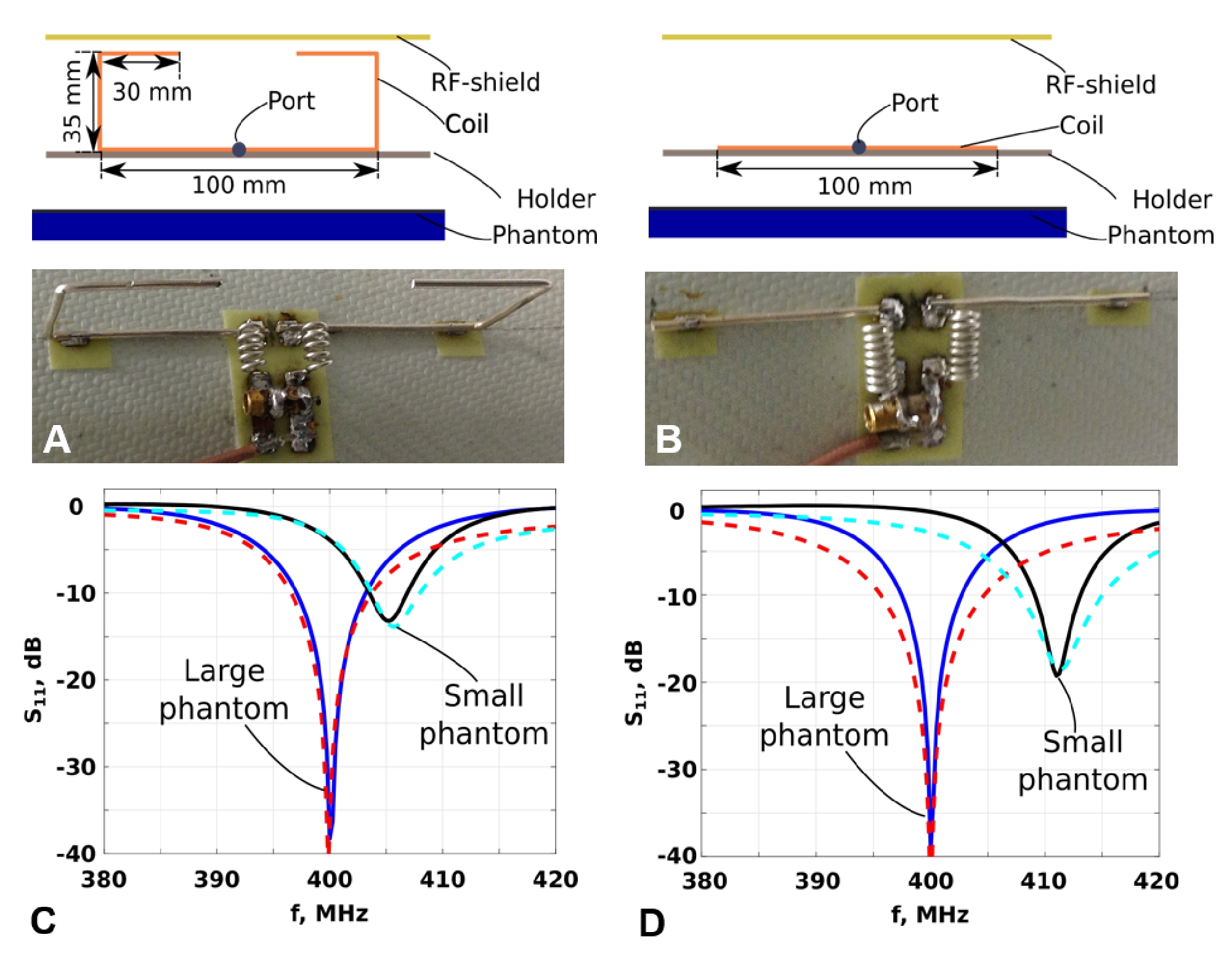
The load dependent frequency shift can be minimized by bending the dipole (Fig.1A) and moving its ends away from the object. This modification shouldn’t substantially affect the RF magnetic field, B1, because ends of the antenna carry a small current. To evaluate the frequency shift due to sample size variation, we used two different in size cylindrical phantoms. We also constructed a straight 100-mm dipole (Fig.1B). The frequency shift measured for the folded dipole was about 2 times smaller than that measured for the straight dipole (Figs.1C and 1D). We numerically evaluated several folded dipoles as well as a vertical loop and a surface loop. We also evaluated SNR of single elements (Fig.2C) and a coupling between a pair of elements placed at 45º from each other. SNR was evaluated as B1-/√P, where P is an RF input power. Finally, we simulated SNR maps (Fig.2D) of several 8-element arrays placed on an elliptical holder (Fig.2B). Table 1 shows results of the entire evaluation. Optimal dipole geometry, i.e. 30-mm folded dipole, was chosen using following criteria: a small frequency shift, good decoupling, and high SNR at the phantom center. Based on optimization we constructed the final array (Figs.3A-D). We also compared the new array to the 16-channel array of similar size with 8 surface loops and 8 Rx-only vertical loops described previously (7). Electromagnetic (EM) simulations of the B1 distribution and local specific absorption rate (SAR) were performed using CST Studio Suite 2015 (CST, Darmstadt, Germany) and the time-domain solver based on the finite-integration technique. Three voxel models were used, i.e. a head/shoulder (HS) phantom (ε=58.6, σ=0.64 S/m at 400 MHz), and two virtual family multi-tissue models, “Duke” and “Ella”. Experimental B1+ maps were obtained using the AFI sequence (8). All data were acquired on a Siemens Magnetom 9.4T human imaging system.Results and Discussion
While B1 distribution
of the straight dipole is symmetrical, the vertical loop B1 map shows a substantial asymmetry (Fig.2C). Folded
dipoles have small asymmetrical contribution increasing with an increase of the
folded portion. Thus, folded dipoles provides a better approximation of
“z-directed”, i.e. dipole-like, currents than vertical loops. As seen from Fig.3E, presence of actively detuned
dipoles did not compromise the decoupling of TxRx surface loops. Also both arrays qualitatively demonstrated
very similar B1+
distributions (Fig.4). Quantitatively, experimental B1+ averaged over the central 20-mm
transversal slab measured 11.46±2.75 μT/√kW and 12.01±2.92 μT/√kW for the dipole and vertical loop arrays, respectively. Thus, our
experimental and numerical evaluations demonstrated that the Tx-performance and SAR of the new array was not
substantially altered by the presence of Rx-dipoles. Maximum increase of the
SAR measured 7.1% for the Duke voxel model. At the same time the dipole
array shows substantially higher (up to 2 times) SNR at the periphery and ~1.17
times higher SNR at the center (Fig.5C).Conclusion
We evaluated usage of optimized 30-mm folded short dipole antennas as elements of a human head Rx-array. Folding the dipole allows decreasing the frequency shift due the head size variation. Addition of Rx-only dipoles doesn’t substantially alter B1+ transmit field and the maximum local SAR. At the same time the new design improves both peripheral and central SNR as compared to the similar 16-element array with Rx-only vertical loops.Acknowledgements
No acknowledgement found.References
1) Wiggins GC et al. Magn Reson Med 2009;62:754–762. 2) Vaidya MV et al. Conc Magn Reson Part B 2014; 44B(3):53-65. 3) Lattanzi R, Wiggins GC, Zhang B, Duan Q et al. Magn Reson Med 2018;79(3):1789-1803. 4) Pfrommer A and Henning A. Magn Reson Med 2018;80(5):2122-2138. 5) Chen G, Lakshmanan K, Sodickson D, and Wiggins GC. Proc. ISMRM 2015, 3133. 6) Zhang B et al. Proc. ISMRM 2017, 4314. 7) Avdievich NI, Giapitzakis IA, and Henning A. NMR in BioMed 2018, 31(2):1-13. 8) Yarnykh VL. MRM 2007;57:192-200.Figures
Figure
1. A) CST
EM simulation model and a photo of the 30-mm folded dipole antenna. B) CST EM
simulation model and a photo of the 100-mm straight dipole antenna.
Experimental (solid line) and simulated (dashed line) S11 plots obtained for the 30-mm folded (C) and
100-mm straight (D) dipoles using two different size cylindrical phantoms,
i.e. 176-mm diameter (large) and 142-mm diameter (small) with electromagnetic properties mimicking the properties
of the human tissue at 400 MHz, i.e. ε=58.6,
σ=0.64 S/m.
In both cases dipole antennas were
matched for the large phantom. Measurements for the small phantom were
performed without any additional adjustment.

Figure 2. A) CST EM simulation setup
for evaluation of single Rx-only elements. B) CST EM simulation setup for
evaluation of SNR of 8-element arrays. C) Simulated SNR maps obtained for three dipole antennas (straight 100-mm, 10-mm folded, and 30-mm folded), a vertical loop (35mmx100mm in size), and a surface loop (100mmx100mm in size) using the large phantom. The
surface loop size corresponds to the size of loops in
a single-row 8-loop array. Simulation setup is
shown in Fig.2A. D)Simulated SNR maps obtained for various 8-element arrays using the elliptical phantom. Simulation setup is shown in
Fig.2B. E) Table comparing
various dipole and loop Rx-elements.

Figure 3. A) EM simulation model of
the new array loaded by the HS phantom. Arrows show elements with the largest S12 value(Tx-mode, Rx-dipoles are detuned)
and the largest noise correlation(Rx-mode). Numbering of elements shown in (B).
C) Photo of the new array with the cover removed. F) Magnified photo of adjacent
elements marked by red (dipoles) and yellow (surface loops) lines. Magnified
area shown in Fig.3C. E) S12 matrix measured for 8
surface TxRx-loops loaded by the HS phantom. White solid line marks worst S12
values (Fig.3A). F) Noise correlation matrix measured using
the HS phantom. White solid lines mark worst noise correlation values(Fig.3A).

Figure
4. A) Central sagittal, transversal, and coronal in-vivo human brain GRE
images obtained using the new 16-element array with dipole Rx-elements. B) Central sagittal and transversal
in-vivo B1+
maps obtained using the new 16-element array. C) Central transversal in-vivo B1+ maps obtained
using the 16-element array with Rx-only vertical loops.

Figure 5. Central sagittal,
transversal, and coronal in-vivo SNR maps obtained using the new 16-element
array with Rx-dipoles (A) and the 16-element array with Rx vertical loops (B).
C) Corresponding ratios of SNR maps shown in Fig.5A to that shown in Fig.5B.