0561
Evaluation of a sleeve monopole antenna array, a novel 16-channel radiative antenna array at 10.5TMyung Kyun Woo1, Lance DelaBarre1, Jingu Lee2,3, Russell Lagore1, Steve Jungst1, Kamil Ugurbil1, and Gregor Adriany1
1Center for Magnetic Resonance Research, Minneapolis, MN, United States, 2Seoul National University, Seoul, Korea, Republic of, 3AIRS medical, Seoul, Korea, Republic of
Synopsis
We designed an elliptical 16-channel transceiver sleeve monopole array for human head imaging at 10.5T and evaluated the performance both in simulation and experiment. The 16-channel sleeve monopole array was compared to 8-channel end-loaded dipole and monopole arrays. Porcine brain images acquired with the sleeve monopole array demonstrate good coverage and performance.
Introduction
Arrays consisting of transmit antennas have the ability to mitigate B1 non-uniformity through optimal combination of phase/amplitude and radio frequency (RF) excitation waveform [1]. At ultrahigh frequencies such arrays are essentially required to achieve acceptable B1+ field uniformity and optimized transmit efficiency [2, 3]. Particularly radiative dipole arrays support the desired high penetration at ultra-high field (UHF), and have been explored successfully particularly for UHF body applications [4-6]. For better field control, transmit efficiency, and specific absorption rate (SAR) it is often desirable to have a greater number of transmit channels. In UHF body applications, 16 dipoles can be arranged around the body with ease. For UHF head applications, however, this is difficult to achieve without suffering unacceptably high inter-element coupling. A sleeve monopole concept has been previously described [7]. We explored this concept for MRI and designed and built a 10.5T 16-CH sleeve monopole array and compared it to an 8-CH end-loaded dipole array and an 8-CH monopole array [8, 9].Methods
Figure 1 shows single element drawings of the dipole, monopole and sleeve monopole (a-c) and coil arrays constructed from these elements (d-i). The 8-CH dipole and monopole array dimensions are: 24cm x 24cm2 and the length of antenna was 16cm for dipole and 12 cm for monopole. The 16-CH sleeve monopole array dimensions are: 20cm x 22cm2 with sixteen equally spaced elements and the antenna length was 20 cm. Floating cable traps were used to suppress the cable sheath currents for all array elements [10]. The floating cable traps are 5 cm long PETG pipe structures 1.2 cm in diameter with a 0.5 cm diameter hole. Four capacitors are used to adjust the frequency. A floating cable trap is positioned at the feed-side of the monopole antenna, and functions similarly to an explicitly grounded sleeve in a sleeve monopole and act as a ground. The current distribution falls to zero on the amplifier side of the traps. All input reflections and coupling coefficients were measured in bench measurements using a 16-CH network analyzer (ZNBT8, Rohde & Schwarz, Munich, Germany). The values for the loaded condition were measured and summarized in Fig.2. Simulated B1+ efficiency and 10g averaged SAR were calculated using XFdtd (REMCOM, State College, PA) with 2mm isotropic resolution as shown in Fig. 3. Experiments were performed at 10.5T and B1+ fields were obtained using an actual flip angle imaging (AFI) sequence for a cylindrical phantom (17 cm diameter and 30.5 cm long) with uniform electrical properties (σ= 0.6 S/m and εr = 49) [11]. B1+ fields were calculated in MATLAB (Mathworks, Inc., Natick, MA, USA) and were normalized to 1 W for B1+ efficiency (µT/√W). Noise correlation matrices were obtained to evaluate crosstalk between elements (Fig.2) [12]. T1- and T2-weighted images of a 37 kg deceased porcine head were acquired with the 16-CH sleeve monopole, Fig.5.Results and Discussion
The 16-CH sleeve monopole array supports tight 2.8 ± 0.65 cm spacing between adjacent elements with acceptable S21 values (from -8.7 dB to -19.6 dB in Fig. 2) without any split resonance peaks. The physical spacing required to achieve similar decoupling values was 9 cm for the 8-CH end-loaded dipole antenna array and 8-CH monopole array. For this reason, it was not practical to construct 16CH versions of dipole or monopole head coils. The proposed sleeve monopole antenna array shows 47% lower B1+ efficiency in simulation and 52% lower B1+ efficiency in experiment compared to the 8-CH monopole antenna array. Similar B1+ efficiency for simulation (9% higher) and experiment (2% higher) was measured compared to an 8-CH end-loaded dipole array (Fig. 3). The B1+ coverage was ~ 10 cm for the 8 CH monopole array, and increased to 21 cm for both the 8-CH end-loaded dipole array and 16-CH sleeve monopole arrays. Compared to the 16-CH sleeve monopole antenna array, the 8-CH monopole antenna array had up to 3 times higher peak 10g SAR values. The 8-CH end-loaded dipole antenna array had 20% lower peak SAR compared to the 16 channel sleeve monopole. The 8-CH monopole antenna array shows the highest B1+ efficiency due to an increased directivity compared to 8-CH end-loaded dipole and 16-CH sleeve monopole antenna arrays. However, the highest SAR at the top of the target limits the usability of the monopole antenna array for human head application at 10.5T.Conclusion
The main advantages of the sleeve monopole antenna array are an increased longitudinal field of view compared to the original monopole antenna array and reduced coupling between elements.Acknowledgements
Support provided by NIH-U01-EB025144, NIH-S10-RR026783, NIH-BTRC-P41-EB015894, NIH-P30-NS076408 and the WM Keck Foundation.References
[1] Adriany G, et al. A 32 channel Transmit/Receive transmission line head array for 3D RF Shimming. In: proceedings of the 15th scientific meeting, International Society for Magnetic Resonance in Medicine, Berlin (2007). [2] Avdievich N, et al. Evaluation of transmit efficiency and SAR for a tight fit transceiver human head phased array at 9.4 T. NMR in Biomedicine 30, e3680 (2017). [3] Shajan G, Kozlov M, Hoffmann J, Turner R, Scheffler K, Pohmann R. A 16‐channel dual‐row transmit array in combination with a 31‐element receive array for human brain imaging at 9.4 T. Magnetic resonance in medicine 71, 870-879 (2014). [4] Raaijmakers A, et al. Design of a radiative surface coil array element at 7 T: the single‐side adapted dipole antenna. Magnetic resonance in medicine 66, 1488-1497 (2011). [5] Wiggins GC, Zhang B, Lattanzi R, Chen G, Sodickson D. The electric dipole array: an attempt to match the ideal current pattern for central SNR at 7 Tesla. In: Proceedings of the 20th Annual Meeting of ISMRM, Melbourne, Australia (2012) [6] Erturk MA et.al Toward imaging the body at 10.5 tesla. Magn Reson Med 77(1):434-443 (2017) [7] David M. Pozar, Microwave engineering. Johm Wiley & Sons (2012) [8] Hong SM, Park JH, Woo MK, Kim YB, Cho ZH. New design concept of monopole antenna array for UHF 7T MRI. Magnetic resonance in medicine 71, 1944-1952 (2014) [9] Woo MK, et al. Extended Monopole antenna Array with individual Shield (EMAS) coil: An improved monopole antenna design for brain imaging at 7 tesla MRI. Magnetic resonance in medicine 75, 2566-2572 (2016) [10] D.A. SEEBER, J. JEVTIC, A. MENON. Floating Shield Current Suppression Trap. D.A. Concepts Magn Reson Part B Magn Reson Eng 21B: 26–31, 2004 [11] Yarnykh VL. Actual flip‐angle imaging in the pulsed steady state: a method for rapid three‐dimensional mapping of the transmitted radiofrequency field. Magnetic Resonance in Medicine: An Official Journal of the International Society for Magnetic Resonance in Medicine 57, 192-200 (2007) [12] Jesmanowicz A, Hyde JS, Froncisz W, Kneeland JB. Noise correlation. Magnetic resonance in medicine 20, 36-47 (1991)Figures
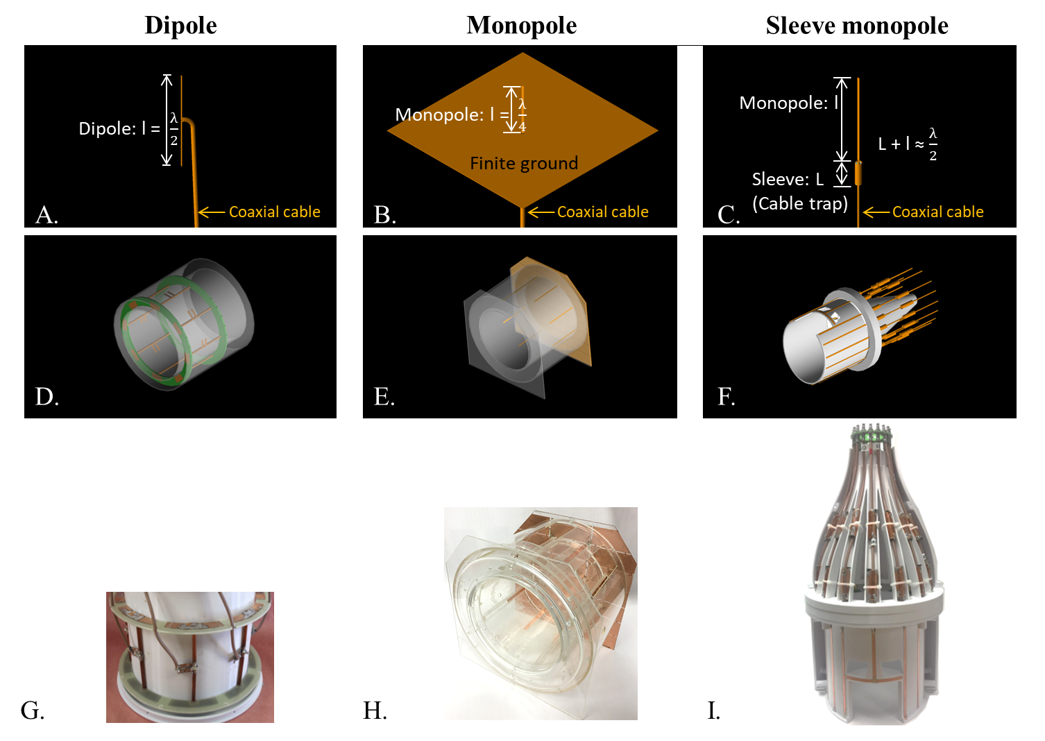
Figure 1. Examples of individual coils elements are shown (A-C). The dipole has two ¼ wavelength poles. The
monopole has just one quarter-wavelenth pole (attached the center conductor)
and a large ground plane. For the
monopole, there is a segmented ground plane positioned superior to the head, at
the position of the white ring in (E).
For the sleeve monopole, there is no such plane, but there are two
floating cable traps (sleeve baluns) that attach to each coax cable. One is just superior to the head, the other
spaced ~ ¼ wavelength behind the first to further impede sheath currents.
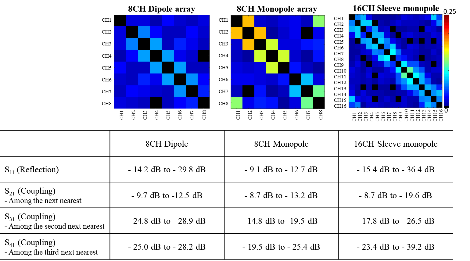
Figure 2. Noise correlation matrices
(upper figures) and S-parameters (lower figures) of reflection and coupling
coefficient in dB for 8CH End-loaded dipole, 8CH Monopole and 16CH Sleeve
monopole arrays.
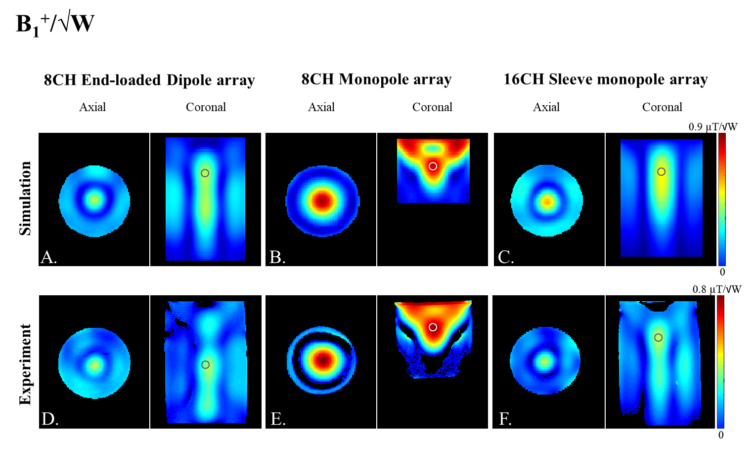
Figure 3. (A-C) Simulation
and (D-F) experimental B1+/√W maps with (A, D) 8 CH
Dipole, (B, E) 8 CH Monopole and (C, F) 16 CH Sleeve monopole arrays in the
axial and coronal plane.
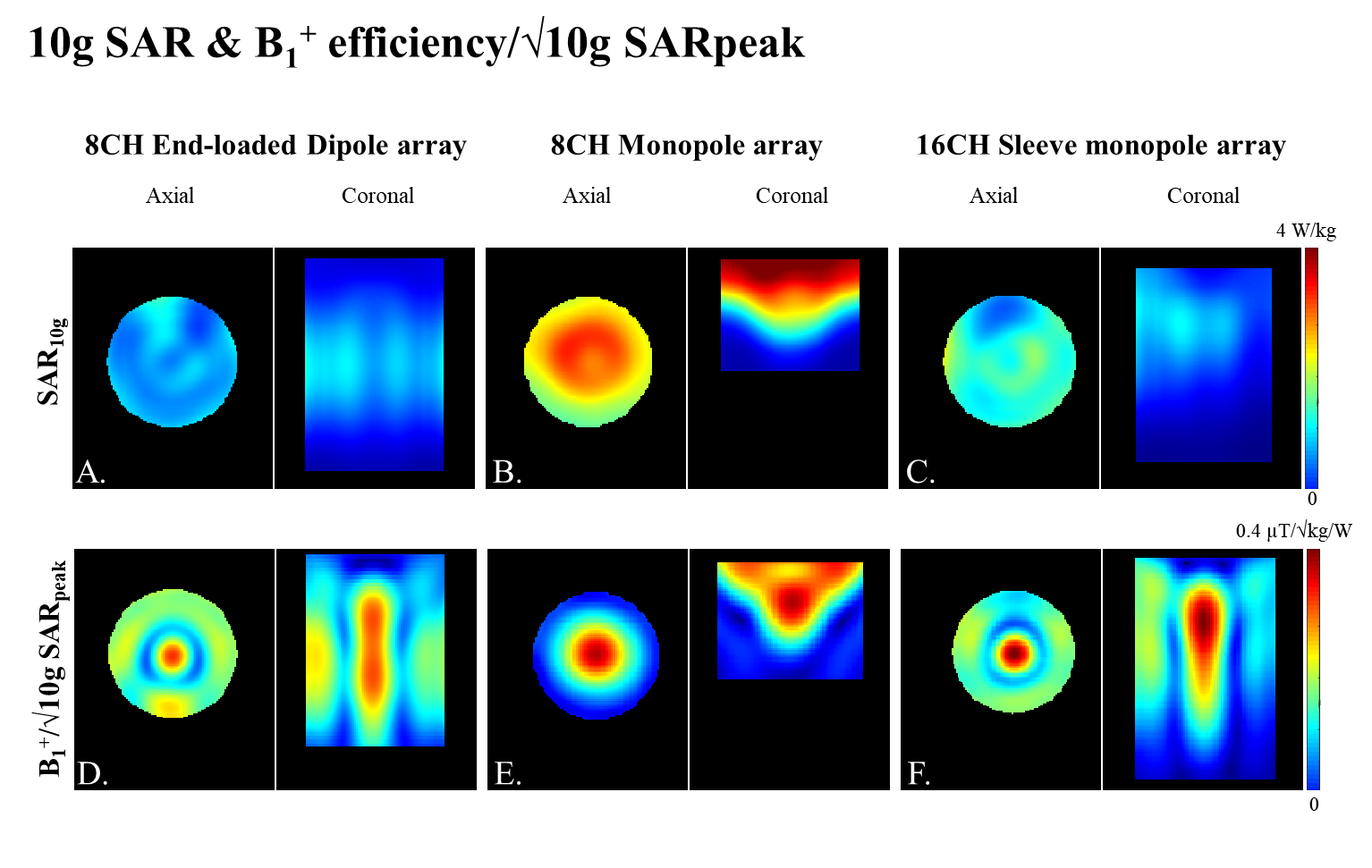
Figure 4. Simulation of (a-c)
10g SAR maps and (d-f) B1+ efficiency/√10g SARpeak with
(A, D) 8 CH Dipole, (B, E) 8 CH Monopole and (C, F) 16 CH Sleeve monopole
arrays in the axial and coronal plane.
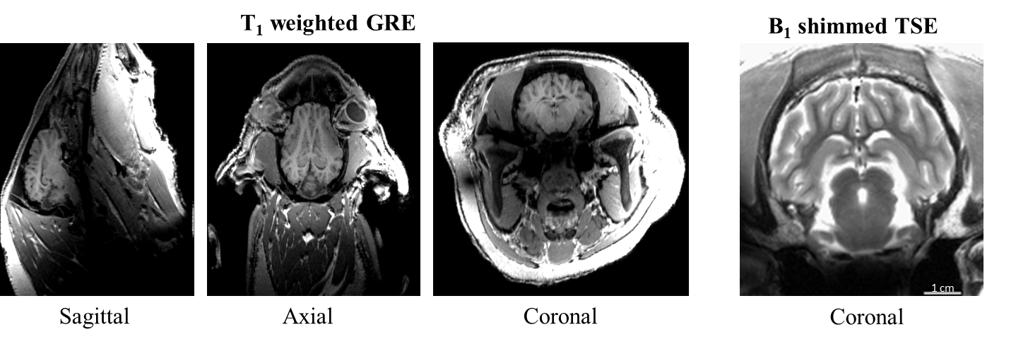
Figure 5. (A-C) 3D T1-weighted
multi-echo GRE of a porcine head with the 16 CH Sleeve monopole array in
sagittal, axial and coronal plane at 10.5T
(TR/TE=3000/2 ms, TI=1500 ms, etl=16 and 0.75x0.75x0.6 mm3
resolution). (D) A high resolution T2-weighted
TSE image (NEX=4) enlarged to show the procine brain (TR/TE = 5000/67 ms, resolution = 0.5x0.5x2 mm3).