0445
Simple Auto-Calibrated Gradient Delay Estimation From Few Spokes Using Radial Intersections (RING) for Interactive Real-time MRI1Institut für Diagnostische und Interventionelle Radiologie, University Medical Center Göttingen, Göttingen, Germany, 2Partner site Göttingen, German Centre for Cardiovascular Research (DZHK), Göttingen, Germany
Synopsis
Radial k-space trajectories are popular for fast imaging but come at the expense of a high sensitivity to system imperfections such as eddy currents and gradient delays. Current gradient delay compensation strategies often demand calibration scans or many spokes for auto-calibration and can be computationally demanding. Here, we use the novel RING approach to estimate the gradient delays for each frame of a real-time cardiac MRI measurement to reliably remove streaking artifacts, even if the slice position is changed interactively.
Introduction and Purpose
In the recent years, radial k-space trajectories are more and more used for fast imaging due to their motion robustness and milder undersampling artifacts. Compared to traditional Cartesian sampling, radial imaging is prone to system imperfections such as eddy current induced gradient delays, which result in k-space mis-centering [1]. To compensate for this many gradient delay correction strategies have been proposed, e.g. [2-7]. However, those methods often either demand calibration scans or require many spokes for auto-calibration and can be computationally demanding. Applications such as interactive real-time MRI [8-10] therefore usually suffer from streaking artifacts, as the gradient delays change when the acquired slice is shifted or rotated. Recently, we have proposed a new auto-calibrating method called RING [11], which allows the estimation of gradient delays from as few as 3 spokes. Hence, RING enables robust gradient delay estimation for each frame. Here, we use an interactive real-time FLASH MRI measurement of a swine heart to study the frame-by-frame evolution of gradient delays during the measurement and show that RING reliably estimates the delays which can be used to remove streaking artifacts.
Theory
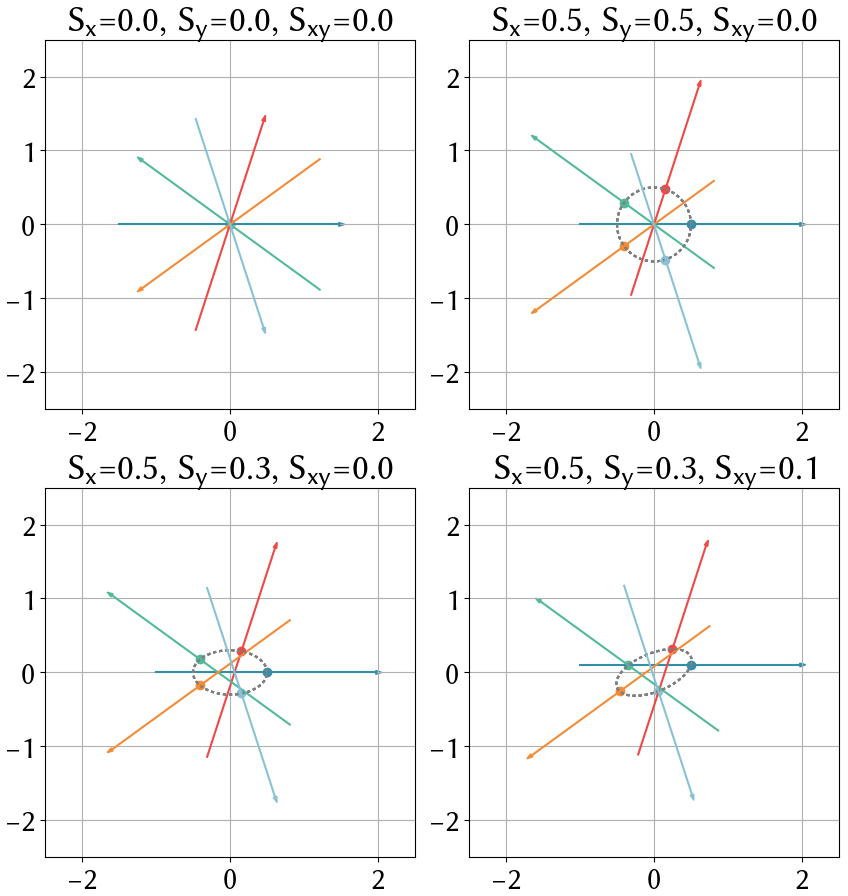
Eddy-currents induce a projection angle ($$$\Theta$$$) dependent shift in k-space [11,12] $$ \delta \boldsymbol{k}(\Theta)=\left(\begin{array}{cc}S_x&&S_{xy}\\S_{xy}&&S_{y}\end{array}\right)\hat{\boldsymbol{n}},\;\;\hat{\boldsymbol{n}}^T=(\cos{\Theta},\sin{\Theta}),$$ with $$$\hat{\boldsymbol{n}}$$$ the normalized projection direction. $$$S_x$$$ and $$$S_y$$$ represent the gradient delays in the axial case and $$$S_{xy}$$$ accounts for a rotated coordinate system. Figure 1 shows a schematic of shifted k-space trajectories for different delays. In [11] we have shown that the intersection points of the spokes can be used to robustly determine the gradient delays $$$S_x$$$, $$$S_y$$$, $$$S_{xy}$$$, which can then be accounted for in the gridding procedure to remove streaking artifacts.
Methods
We performed a 30 second random RF spoiled [13] interactive real-time FLASH MRI measurement on a swine heart (FOV = 256x256 mm, base-resolution 128, 21 evenly distributed spokes per frame, 5 interleaved spoke patterns) and interactively changed the slice position. We calculated the gradient delays for each frame to observe their changes when the measured slice is shifted or rotated. We furthermore reconstructed the real-time movie using radial NLINV [14,15] with frame-by-frame gradient delay correction using RING and compare it to a reconstruction where the gradient delays are estimated only once for the first frame and used throughout the entire time series. The gradient delay estimation and image reconstruction was performed using BART [16].
Results and Discussion
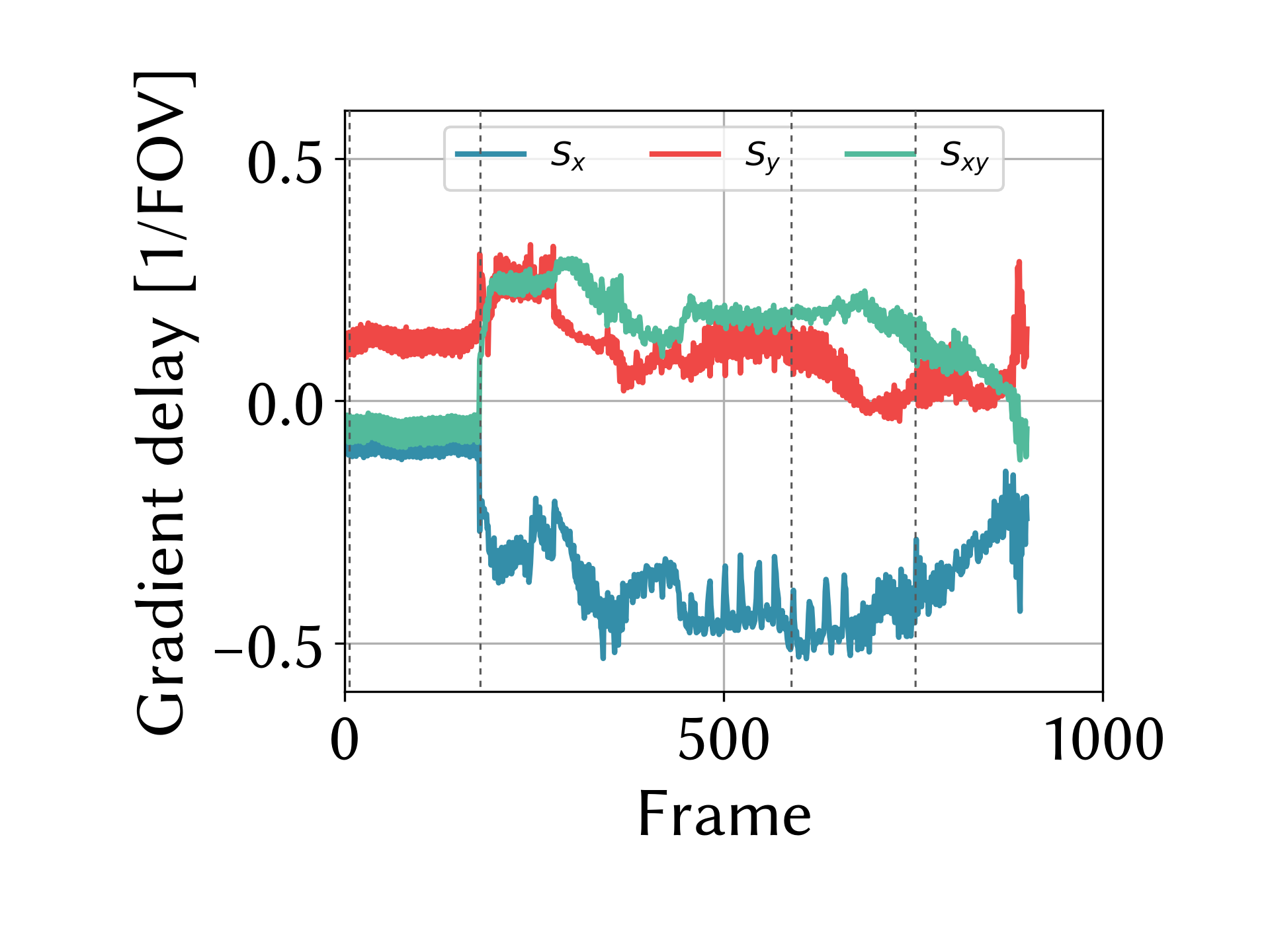
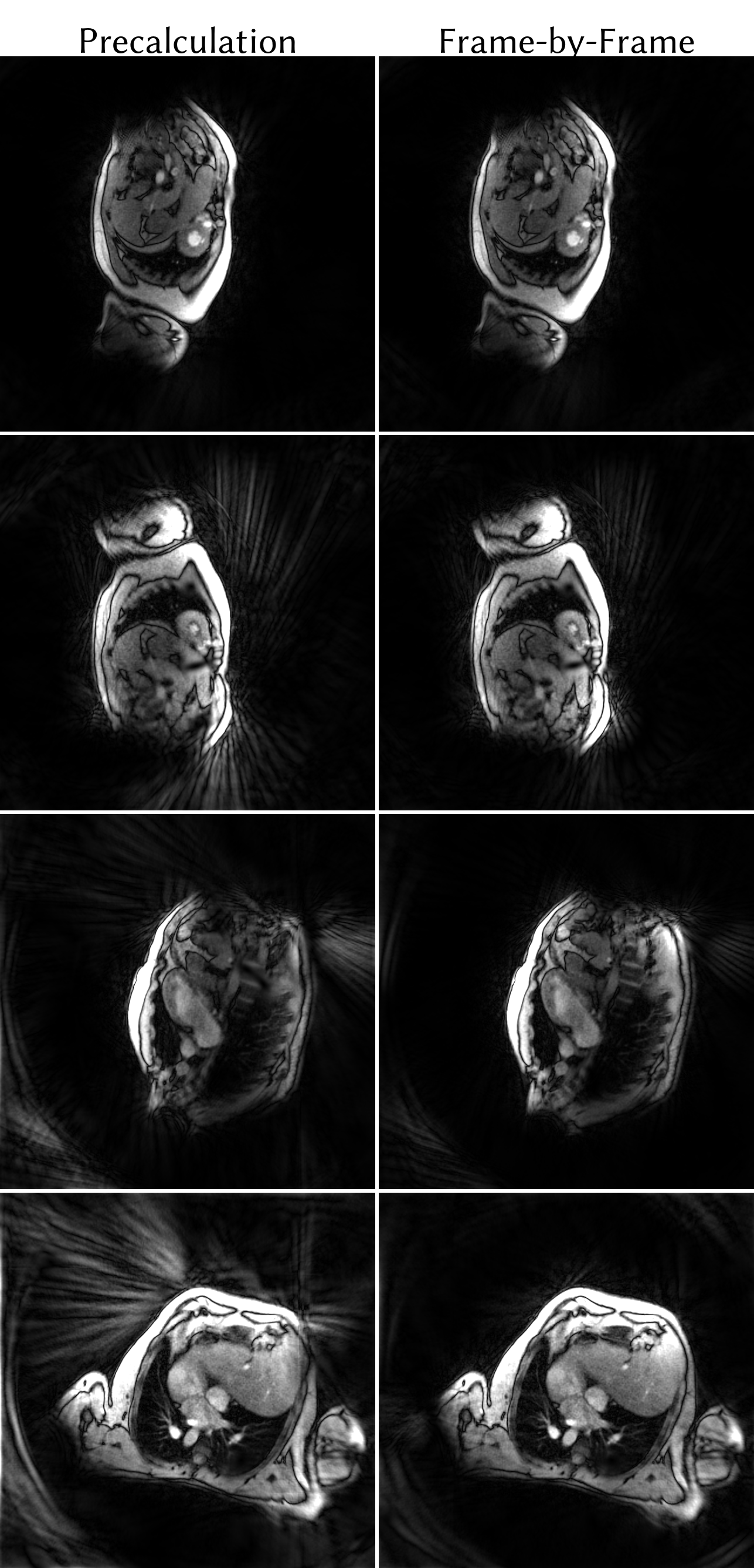
Figure 2 shows the evolution of the gradient delays $$$S_x$$$, $$$S_y$$$ and $$$S_{xy}$$$ during the measurement. Whereas the slice position was the same for the first 177 frames, it was abruptly changed in frame 178 and then continuously altered. The interactive displacement of the acquired slice causes the gradient delays to vary in time. Figure 3 (left) shows representative frames of the dynamic imaging movie reconstructed with radial NLINV where the gradient delay estimation was performed only once at the beginning of the measurement. Figure 3 (right) depicts the corresponding images with frame-by-frame gradient delay correction using RING. The top row showing frame 5 looks suitable for both cases, as the slice position has not yet been changed, hence the precalculated gradient delay is still valid. Starting with frame 178, where the slice position was suddenly changed, the reconstructions with precalculated gradient delays exhibit pronounced artifacts. In contrast, the frame-by-frame gradient delay estimation with RING determines the new gradient delays for the shifted and rotated slices well and significantly reduces the streakings.
Conclusion
We have demonstrated that the RING gradient delay correction can be applied frame-by-frame to a real-time MRI measurement with interactive changes to the slice position to reliably remove streaking artifacts.Acknowledgements
No acknowledgement found.References
[1] Peters DC, Derbyshire JA, McVeigh ER. Centering the projection reconstruction trajectory: Reducing gradient delay errors. Magn. Reson. Med. 2003; 50:1–6. [2] Barmet C, Zanche ND, Pruessmann KP. Spatiotemporal magnetic field monitoring for MR. Magn. Reson. Med. 2008; 60:187–197. [3] Vannesjo SJ, Haeberlin M, Kasper L, Pavan M, Wilm BJ, Barmet C, Pruessmann KP. Gradient system characterization by impulse response measurements with a dynamic field camera. Magn. Reson. Med. 2013; 69:583–593. [4] Jang H, McMillan AB. A rapid and robust gradient measurement technique using dynamic single-point imaging. Magn. Reson. Med. 2016; DOI: 10.1002/mrm.26481. [5] Wech T, TranGia J, Bley TA, Köstler H. Using self-consistency for an iterative trajectory adjustment (SCITA). Magn. Reson. Med. 2015; 73:1151–1157. [6] Block KT, Uecker M. Simple Method for Adaptive Gradient-Delay Compensation in Radial MRI.Reson. Med. 19, Montreal, 2011. p. 2816. [7] Rosenzweig S, Holme HCM, Wilke RN, Uecker M. Extending the Simple Method for Adaptive Gradient-Delay Compen- sation in Radial MRI. In: Proc. Intl. Soc. Mag. Reson. Med. 26, Paris, 2018. [8] Kerr AB, M. PJ, S. HB, C. LK, J. HC, H. MC, Albert M, G. ND. Real-time interactive MRI on a conventional scanner. Magn. Reson. Med. 1997; 38:355–367. [9] Unterberg-Buchwald C, Ritter CO, Reupke V, Wilke RN, Stadelmann C, Steinmetz M, Schuster A, Hasenfuß G, Lotz J, Uecker M. Targeted endomyocardial biopsy guided by real-time cardiovascular magnetic resonance. J. Cardiov. Magn. Reson. 2017; 19:45. [10] Yang PC, Kerr AB, Liu AC, Liang DH, Hardy C, Meyer CH, Macovski A, Pauly JM, Hu BS. New real-time interactive cardiac magnetic resonance imaging system complements echocardiography. J Am Coll Cardiol 1998; 32:2049 – 2056. [11] Rosenzweig S, Holme HCM, Uecker M, Simple Auto-Calibrated Gradient Delay Estimation From Few Spokes Using Radial Intersections (RING), Magn. Reson. Med. 2018, 10.1002/mrm.27506.
[12] Moussavi A, Untenberger M, Uecker M, Frahm J. Correction of gradient-induced phase errors in radial MRI. Magn. Reson. Med. 2013; 71:308–312. [13] Roeloffs V, Voit D, Frahm J. Spoiling without additional gradients: Radial FLASH MRI with randomized radiofrequency phases. Magn. Reson. Med. 2016; 75:2094-2099. [14] Uecker M, Hohage T, Block KT, Frahm J. Image reconstruction by regularized nonlinear inversion—joint estimation of coil sensitivities and image content. Magn. Reson. Med. 2008; 60:674–682. [15] Uecker M, Zhang S, Frahm J. Nonlinear inverse reconstruction for real-time MRI of the human heart using undersampled radial FLASH. Magn. Reson. Med. 2010; 63:1456–1462. [16] Uecker M, Ong F, Tamir JI, Bahri D, Virtue P, Cheng JY, Zhang T, Lustig M. Berkeley advanced reconstruction toolbox. In: Proc. Intl. Soc. Mag. Reson. Med. 23, Toronto, 2015. p. 2486.
Figures