0437
Over-overlapped Loop Arrays1College of nuclear equipment and nuclear engineering, Yantai University, Yantai, China, 2Institute of Imaging Science, Vanderbilt University, Nashville, TN, United States, 3Department of Radiology and Radiological Sciences, Vanderbilt University, Nashville, TN, United States, 4Department of Biomedical Engineering, Vanderbilt University, Nashville, TN, United States
Synopsis
Loops are usually overlapped by approximately 10% in
Introduction:
The loop coil consisting of a series inductance
and capacitance is a mainstay in RF array designs 1. Loops are
usually overlapped by approximately 10% in area to minimize the mutual
inductive coupling. Due to geometrical constraints, the size of each loop has
to be reduced to increase the numbers of coils in an array. In this work, we
propose a simple loop array design that achieves over-overlap as well as low
reactive/resistive coupling. Numerical results show that the proposed
over-overlapped loop arrays could increase the performance of parallel imaging and
SNR.Methods:
Figure 1a shows a schematic of a single conventional loop coil with a uniform capacitance distribution along the conductor and thus uniform current distribution (Figure 1c). Figure 1b shows a schematic of a self-decoupled loop coil 2 with a tailored capacitance/current distribution, where the current is strong near the feed port while weak near its opposite side (Figure 1d). As shown in previous work, this tailored current distribution is helpful to reduce inter-element coupling and provide more freedom for coil layouts. In this specific study, both the conventional coil and the self-decoupled coil have a diameter of ~8.7 cm and a conductor width of 0.5 cm. Both coils were wrapped around a 15-cm-diameter cylindrical water phantom (б=0.6 S/m and ξr=78) separated by 0.8 cm. Their calculated axial B1- fields in the central slice are shown in Figures 1g-h.
Next, we analyzed the inter-element isolation of two conventional overlapped coils and two self-decoupled coils overlapped to a greater degree (over-overlapped). For the same coverage, an over-overlapped array can be made with more coil elements without the compromise of smaller coil size. In this study, a conventional array is 8 coils was compared to an over-overlapped array of 12. The SNR and g-factor of the 8-ch array were calculated from simulation results and compared to those of a 12-ch over-overlapped array. Simulations were performed using HFSS (ANSYS, Canonsburg, PA, USA). In all simulations, coil elements were tuned to the Larmor frequency of 7T (298 MHz) and matched to 50 Ω. The SNR was calculated by $$$ \sqrt{B_1^{-H} × ψ × B_1^- } $$$3,4 and normalized to the maximum value, where B1- is the reception B1 field and Ψ is the noise matrix. The SENSE g-factor is calculated following a standard definition 5.
Results:
Figures 2a-b show the layout of two conventional loops (~10% overlap) and two over-overlapped loops (~40% overlap). Similar to the magnetic field, the electric (E-) field in the sample is stronger near the feed port. To separate the adjacent loops' E-field and to reduce their resistive coupling, the feed ports of two adjacent self-decoupled coils were positioned in opposite sides. Figures 2c-f show the current distributions of an individual loop from a pair of conventional loops and a pair of over-overlapped loops.
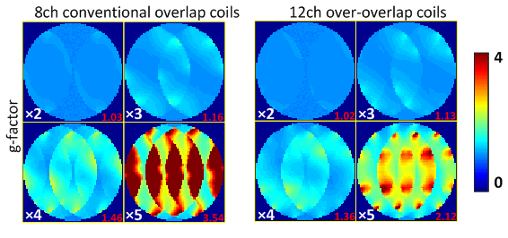
For both the conventional 8-ch array and the 12-ch over-overlapped array, the worst-case coupling is approximately -13 dB and from adjacent loops. Figures 3e-f show the individual B1- maps of the two arrays. Figures 4a shows their SNR comparison and Figure 4b shows the 1-D SNR profile along white dotted lines in Figure 4a. Compared to the conventional 8-ch array, the over-overlapped 12-ch array has improved SNR in the surface area and the same SNR at the center area (overall SNR improvement 20%). Figures 5 shows the g-factor comparison between the two arrays. The g-factor maps in Figure 5 are proportional to the accelerated image SNR, and they indicate that the SNR can be significantly improved with the over-overlapped design, especially at high acceleration factor.
Discussions and Conclusion:
We describe an over-overlapped loop array design with considerable
SNR and parallel imaging performance improvement arising from the increased
coil number possible. The basic element of the over-overlapped array is based
on our previously reported self-decoupled coil. A ~40% overlap was chosen in
this study, but this area can vary across a range from 0 to 50%. Another potential
challenge in an over-overlapped array is the coupling between non-adjacent
elements since they are positioned much closer. However, this is not a problem
for self-decoupled coils since the next-adjacent loops are intrinsically
decoupled where their electric coupling cancels the magnetic coupling. By
reducing the loop size to 2/3, the coil number of a conventional loop array can
increase from 8 to 12. However, unlike the over-overlapped array described here
that is based on self-decoupling loops, the decoupling performance of a
conventional array would be quite sensitive to the coils' overlap area and separation.
The acceptable inter-element isolations were achieved without preamplifier
decoupling, so the over-overlapped design can be directly applied to transmit
arrays.Acknowledgements
Dr. Ming Lu's work was supported by Natural Science Foundation of Shandong Province (ZR2016AQ02) .References
1. Roemer, Peter B., et al. "The NMR phased array." Magnetic resonance in medicine 16.2 (1990): 192-225.
2. Yan, Xinqiang, John C. Gore, and William A. Grissom. "Self-decoupled radiofrequency coils for magnetic resonance imaging." Nature communications 9.1 (2018): 3481.
3. Edelstein, W. A., et al. "The intrinsic signal‐to‐noise ratio in NMR imaging." Magnetic resonance in medicine 3.4 (1986): 604-618.
4. Kellman, Peter, and Elliot R. McVeigh. "Image reconstruction in SNR units: a general method for SNR measurement." Magnetic resonance in medicine 54.6 (2005): 1439-1447.
5. Pruessmann, Klaas P., et al. "SENSE: sensitivity encoding for fast MRI." Magnetic resonance in medicine 42.5 (1999): 952-962.
Figures