0436
Compact Self Grounded Bow Tie Antenna Resonator for Cardiac MRI at 7.0 Tesla1Berlin Ultrahigh Field Facility, Max-Delbrück Center for Molecular Medicine in the Helmholtz Association, Berlin, Germany, 2MRI.TOOLS GmbH, Berlin, Germany, 3Physikalisch-Technische Bundesanstalt (PTB), Berlin, Germany, 4Experimental and Clinical Research Center (ECRC), a joint cooperation between the Charité Medical Faculty and the Max-Delbrück Center for Molecular Medicine, Berlin, Germany
Synopsis
A compact dielectric resonator antenna array was developed for cardiovascular MRI at 7.0T MRI. The antenna building block is based on the concept of a self-grounded bow-tie (SGBT) antenna placed inside a resonator cavity filled with deuterium oxide. This approach ensures light-weight design and affords high-density RF arrays, which constitutes a major advantage over current state-of-the-art electric dipole configurations. The proposed high-density SGBT transceiver array provides ample parallel imaging and real time imaging capabilities. It contributes to the technological basis for the future clinical assessment of parallel transmit techniques designed for ultrahigh field cardiac MR.
Purpose
A plethora of reports
eloquently describe cardiovascular MRI (CMR) at 7.0T, including the first
clinical applications. A crucial factor of CMR at ultrahigh fields is the fact that
the upper torso is especially susceptible to non-uniformities in the RF
transmission field (B1+) due to the short wavelength. To
address constructive and destructive interferences, pioneering RF antenna
arrays have employed electric dipoles. Electric dipoles have a characteristic
linearly polarized current pattern, in which RF energy is directed
perpendicular to the dipole, along the Poynting vector, to the subject 1. To enable efficient power transmission, the dipole
length needs to be adjusted to the transmission frequency. Consequently, the
antenna size can be as long as 30cm for a fragmented dipole at 297MHz considering
reasonable B1+ and specific absorption rate values (SAR) 2. This geometric constraint imposes a severe
limitation for the design of high-density transceiver arrays confined to
cardiac fields of view. To circumvent this limitation, dielectric resonators offer
a viable alternative. This work proposes a small self-grounded bow-tie (SGBT)
antenna placed in a light-weight resonator cavity. We demonstrate the
feasibility of this design in a high density array, both in phantom and in-vivo cardiac MR.Methods
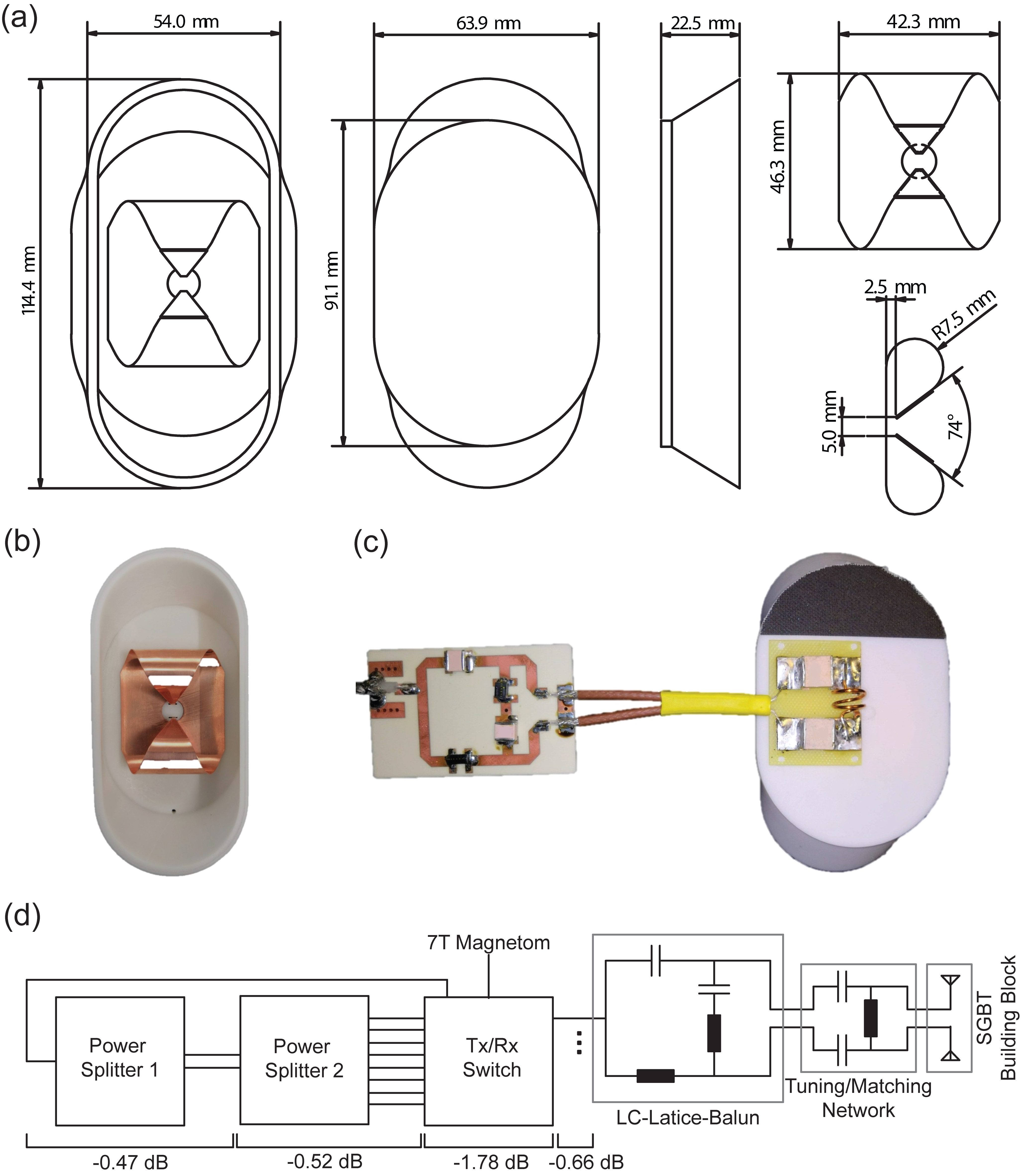
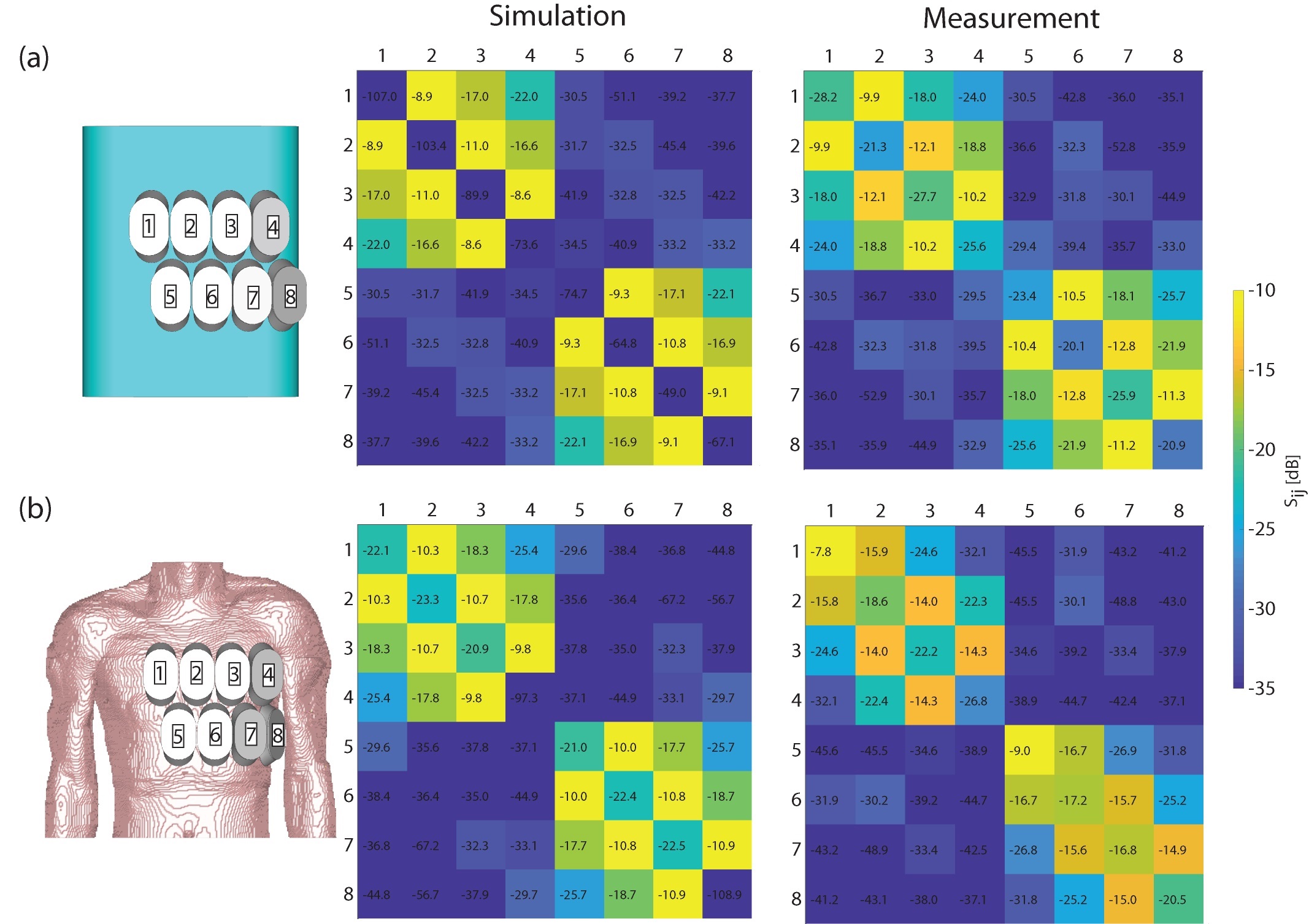
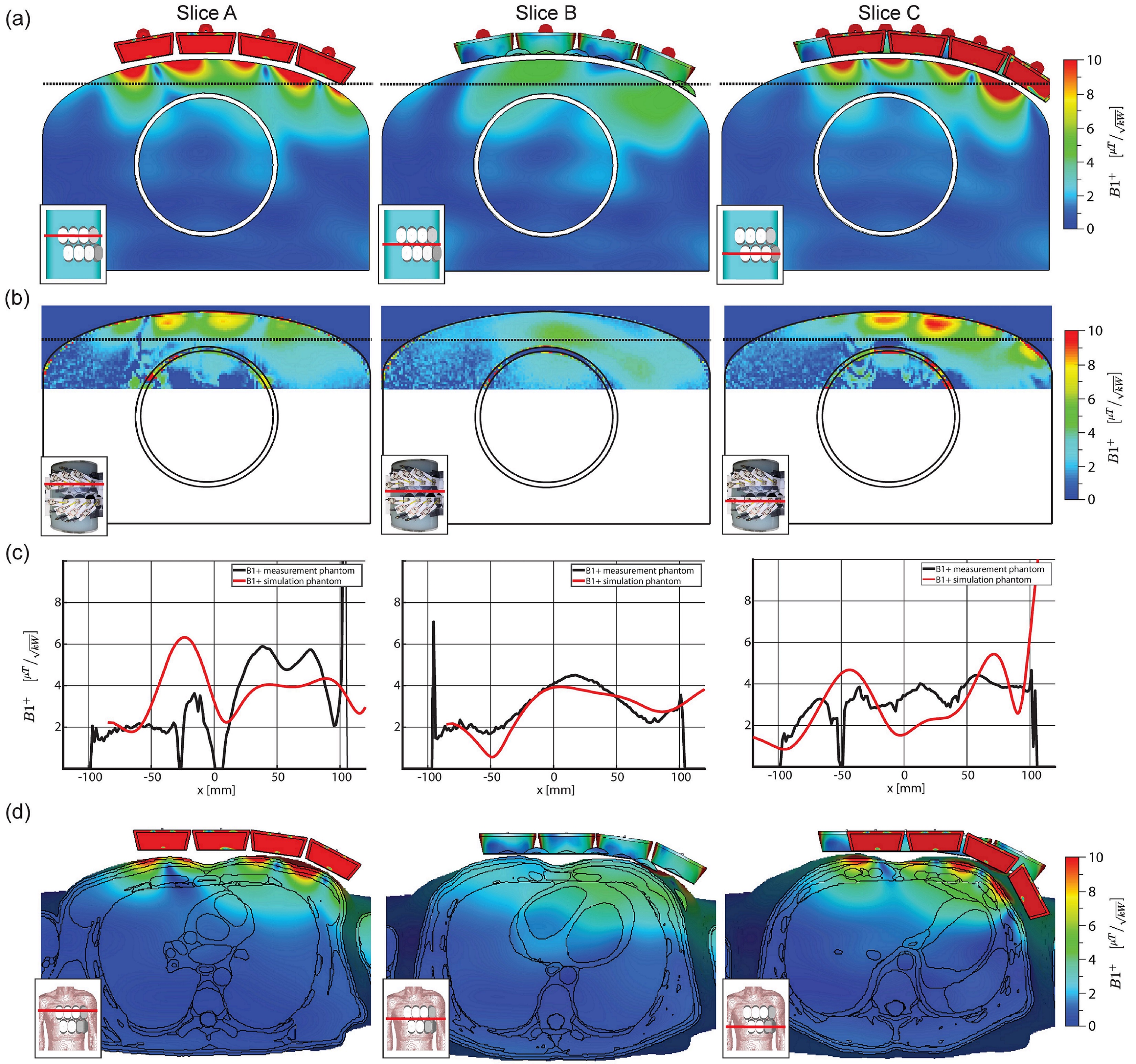
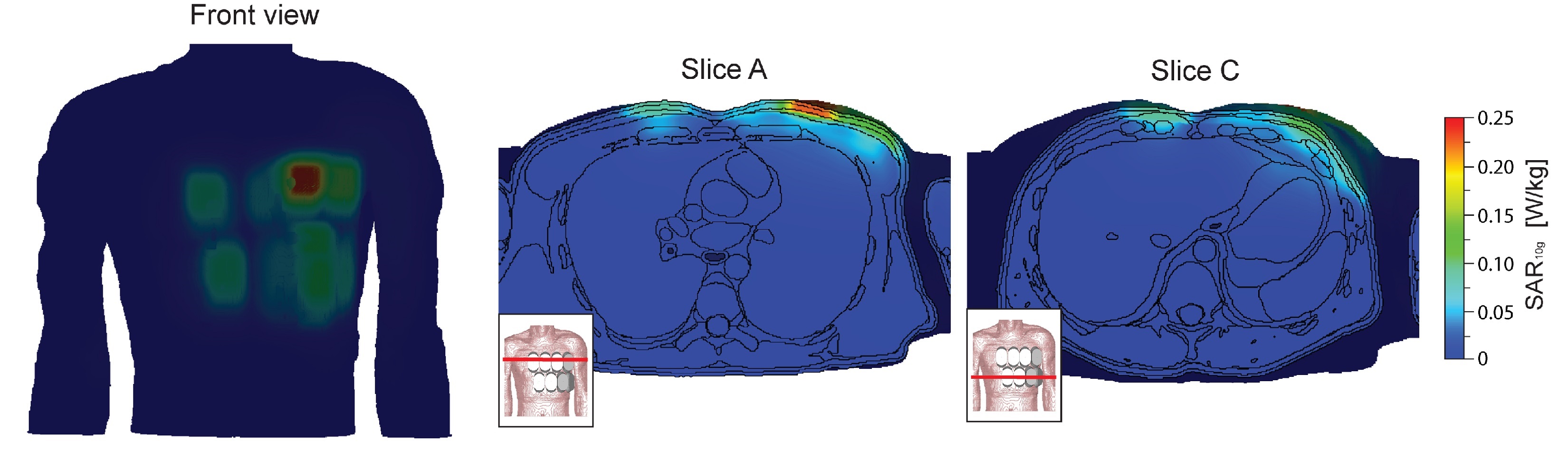
The RF building block comprises a SGBT antenna immersed in 99.9% D2O (Sigma Aldrich GmbH, Munich, Germany) for wavelength shortening. Tuning air-coil inductance and nonmagnetic matching capacities were used to ensure a resonance frequency of 298MHz. An LC-Lattice-Balun based design was used as a balanced-unbalanced transformer tuned to 298MHz, with a common mode rejection ratio of –40dB. The antenna and building block geometry was optimized with CST Microwave Studio’s (CST Studio Suite 2018, CST – Computer Simulation Technology GmbH, Darmstadt, Germany) implemented genetic optimization algorithm, to operate at a broad frequency band ranging from 250-516MHz. Electromagnetic field (EMF) simulations of the antenna array were performed on a tissue mimicking torso phantom (εr=78.4 and σ=0.64S/m) and on the torso of the human voxel model Duke 3, where the latter was used for B1+-field optimization in the heart. An array of eight elements was setup for proof-of-principle studies (Figure2). A phase shimming approach was implemented in MATLAB (MathWorks, Natick, USA) for a phase setting tailored for a uniform and efficient excitation in the target region. The B1+-field deduced from EMF simulations was validated with pre-saturation based B1+-mapping. SAR calculations at 298MHz were normalized to 1W input power and averaged over 10g according to IEEE/IEC-standard 62704-1 4. Phantom and in vivo studies were conducted with a 7.0T whole-body MRI system (MAGNETOM, Siemens Healthineers, Erlangen, Germany) 5.Results
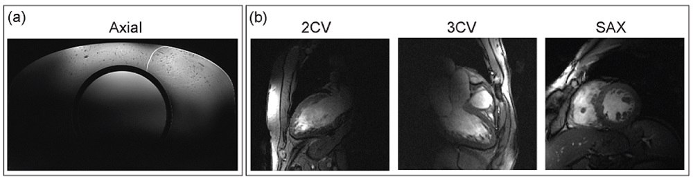
The proposed light-weight building block (m=150g, size=114.4x54.0x22.5mm³) includes an SGBT inside a resonator cavity, a tuning and matching network, and a balun (Figure 1). The scattering matrix of the antenna array for the torso phantom, the torso of Duke and a healthy subject is shown in Figure 2. The antenna bandwidth at -10dB was >5.4MHz, with a reflection coefficient of Sii<-16.8db and a coupling coefficient of Sij<-8.9dB for all simulations and measurements, except of two elements in the in vivo measurements (Figure 2). The quality factor ratio of loaded to unloaded was 0.64 and the square root of the load power absorption was 60%. B1+-shimming yielded a phase setting of [0 -328 -11 -12 -344 -338 -342 -318]° affording a homogeneity of 56% and a mean B1+-field of 3μT/√kW for the heart of the human voxel model Duke. B1+ simulations and B1 measurements (Figure 3) revealed a low difference for the torax phantom, offering transmission fields of up to 4μT/√kW in the heart region. Peak SAR, including the losses in the signal chain, was found to be 0.25W/kg (Figure 4) at 1W input power, which limits the forward power to 40W according to IEC guidelines 6. Figure 5 surveys end-diastolic three chamber, two chamber and short axis views of the heart obtained with a 2D CINE FLASH protocol that supports a spatial resolution of (1.4x1.4x4.0) mm³.Discussion and Conclusion
The proposed light-weight SGBT building block pushes the boundaries of RF antenna design and enables the use of high density arrays. The building block size is reduced by a factor of 16 versus commonly used fractionated dipoles. The SGBT volume is reduced by 55% or 72% versus state-of-the-art SGBT (107x78x31mm³) or bow tie (150x70x40mm³) antenna configurations 7,8. The 8 channel array presented here facilitates cardiac MRI at 7.0T, affording an increase in channel density by a factor of 2 over a bow tie cardiac array 8 and a factor of 16 over a fractionated dipole array 2. The high density, together with the low reflection and good decoupling facilitates a high transceiver channel count for massively accelerated cardiac MR.Acknowledgements
This project was funded in part by an advanced ERC grant (EU project ThermalMR: 743077).References
1. Winter L, et al. Design and Evaluation of a Hybrid Radiofrequency Applicator for Magnetic Resonance Imaging and RF Induced Hyperthermia: Electromagnetic Field Simulations up to 14.0 Tesla and Proof-of-Concept at 7.0 Tesla. PLoS One. 2013;8(4):e61661.
2. Raaijmakers AJE, et al. The fractionated dipole antenna: A new antenna for body imaging at 7 Tesla. Magn Reson Med. 2016;75(3):1366-1374.
3. Christ A, et al. The Virtual Family - Development of surface-based anatomical models of two adults and two children for dosimetric simulations. Phys Med Biol. 2010;55(2).
4. IEEE 62704-1-2017 - IEC/IEEE International Standard for Determining the Peak Spatial Average Specific Absorption Rate (SAR) in the Human Body from Wireless Communications Devices, 30 MHz - 6 GHz. Part 1: General Requirements for using the Finite Differenc. 2017.
5. Yarnykh VL. Actual flip-angle imaging in the pulsed steady state: A method for rapid three-dimensional mapping of the transmitted radiofrequency field. Magn Reson Med. 2007;57(1):192-200.
6. Medical electrical equipment - Part 2-33: Particular requirements for the basic safety and essential performance of magnetic resonance equipment for medical diagnosis in Medical Electrical Equipment. Int Electrotech Comm. 2013.
7. Winter L, et al. Ultrahighfield, One for all: Ultra-wideband (279-500MHz) self-grounded bow-tie antenna for MR, and thermal. ISMRM-ESMRMB; 2018:#4281.
8. Oezerdem C, et al. 16-channel bow tie antenna transceiver array for cardiac MR at 7.0 tesla. Magn Reson Med. 2016;75(6):2553-2565.
Figures