0435
Dielectric resonator for targeted breast MRI at 3T1Department of Nanophotonics and Metamaterials, ITMO University, Saint Petersburg, Russian Federation, 2Department of Radiology, Vreden Russian Institute of Traumatology and Orthopedics, Saint Petersburg, Russian Federation, 3Giricond Research Institute, Ceramics Co., Ltd., Saint Petersburg, Russian Federation, 4Department of Radiology, Leiden University Medical Center, Leiden, Netherlands
Synopsis
A novel concept for targeted MRI that can be directly integrated into an existing clinical system is proposed and demonstrated for 3T breast imaging. A practical demonstration of the concept features a dielectric resonator, based on a composite material with a very high permittivity that is electromagnetically coupled to the birdcage body coil. In vivo breast imaging with the proposed resonator showed 70% higher signal-to-noise ratio and reduced motion
Introduction
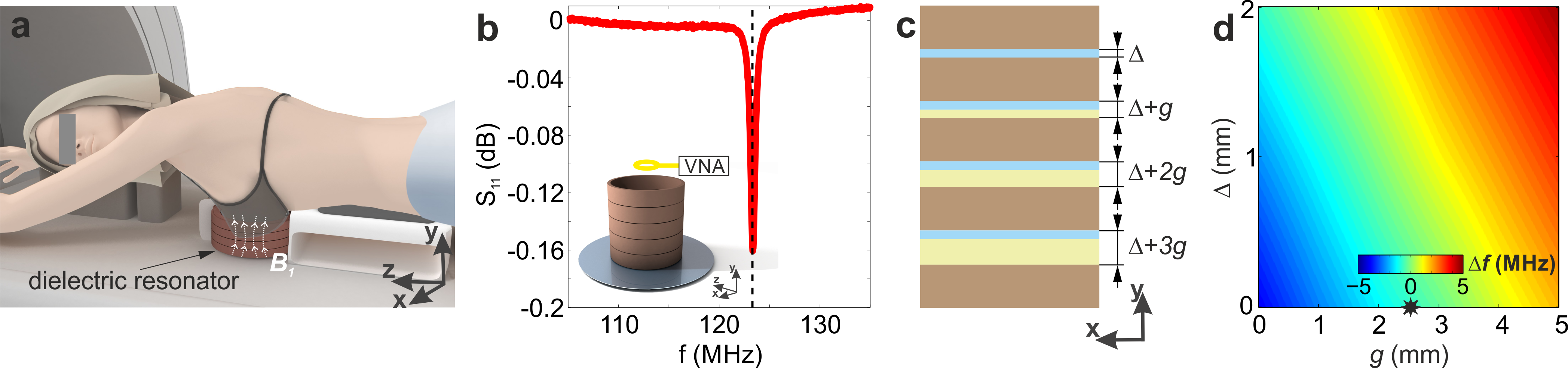
Here we describe and demonstrate experimentally a novel concept of targeted clinical MRI applied to breast imaging. The idea is based on a local redistribution and passive focusing of the radiofrequency (RF) magnetic flux of the birdcage body coil (BC) using electromagnetic coupling with a subwavelength dielectric resonator (DR) surrounding the target area (Figure 1а).Methods
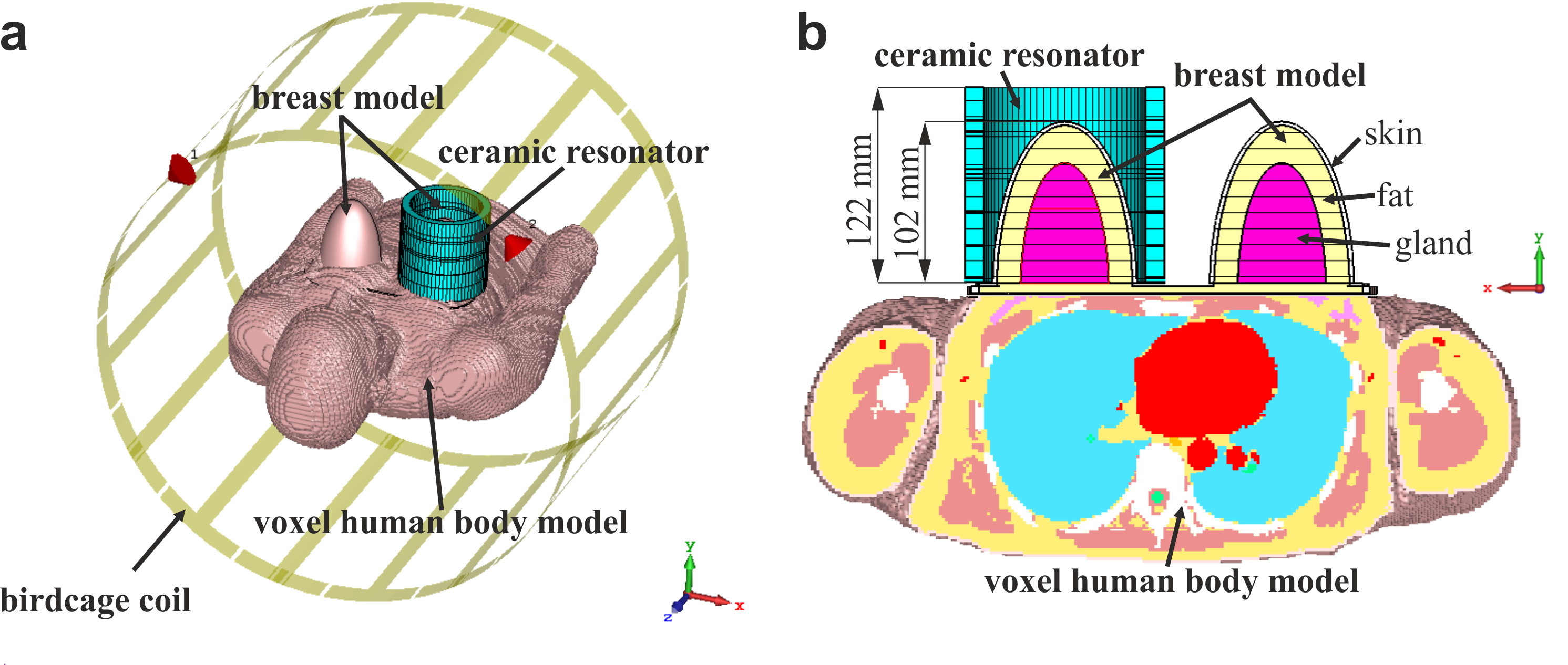
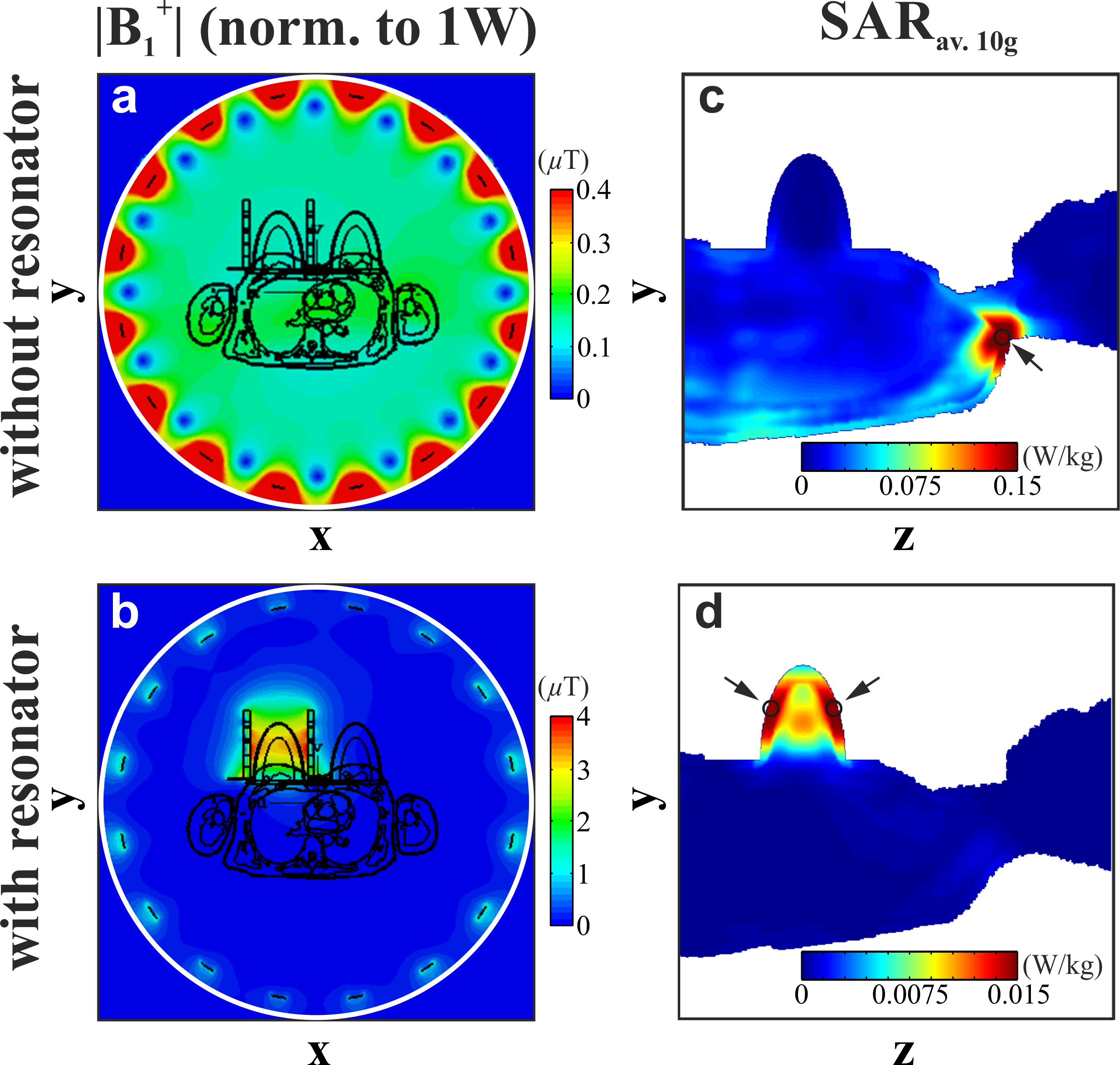
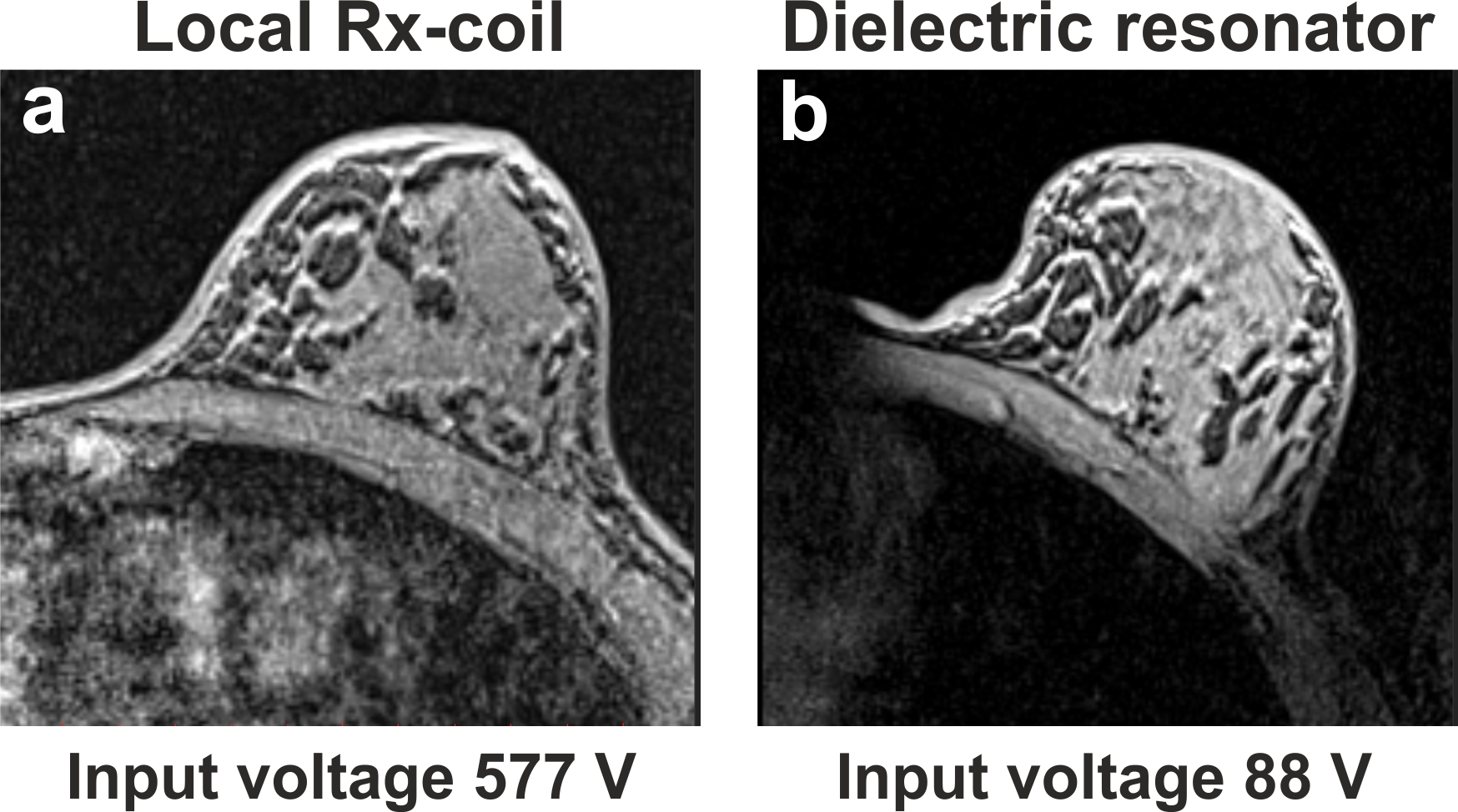
A proposed concept was based on a passive focusing of the B1+ field of a BC using a high permittivity DR.1,2 The resonator was constructed from five ceramic discs with relative permittivity $$$\epsilon$$$∼1000 and tan$$$\delta$$$∼0.0004 (at 1 MHz) and the following dimensions: inner diameter 101.5 mm, outer diameter 124.4 mm, height of each disk 20 mm. The frequency of the resonator’s $$${\textrm{TE}}_{01\delta}$$$-mode3 was tuned to 123.25 MHz (the Larmor frequency for Siemens 3T MR scanners) by changing the spacing between the ceramic disks (Figure 1b). As spacers, we have used several thin disks made of plexiglass with $$$\epsilon$$$spacer∼3.5 and $$$\sigma$$$spacer=0.02 S/m that have the same inner and outer diameters as the ceramic disks. To preserve the efficiency of the DR with proximity to the chest a thin metallic disk made of 14$$$\mu$$$m-thick aluminum foil was added (Figure 1b). All numerical simulations were performed in CST Microwave Studio 2017. The operational frequency of the $$${\textrm{TE}}_{01\delta}$$$-mode as a function of the air gaps between the adjacent disks (parameters ∆ and g in Figure 1c) was calculated using a parametric sweep. Electromagnetic modeling of the DR was performed using a voxelized female human body model placed in a standard BC (Figure 2a). A layered breast model was created consisting of the following tissue types (Figure 2b): skin ($$$\epsilon$$$=72.93, $$$\sigma$$$=0.49 S/m), fat ($$$\epsilon$$$=5.6, $$$\sigma$$$=0.03 S/m), gland ($$$\epsilon$$$=67, $$$\sigma$$$=0.8 S/m). For a reference, the standard BC was simulated with the same body model at the same central position, but without the resonator. The B1+ field distributions were normalized to 1W of total accepted power. The SARav.10g distributions were normalized to the same average B1+ in the breast area. The effect of the resonator on the BC transmit performance was evaluated by comparison of the ratio $$$ {{| \textrm{B}_{1, \textrm{RMS}}^+|}/{\sqrt{ \textrm{psSAR}_{ \textrm{av.10g}}}}}$$$ in the presence of the resonator to the ratio with the BC alone, where the $$$| \textrm{B}_{1, \textrm{RMS}}^+|$$$ field value was spatially averaged over the targeted area (RMS=root mean square) and psSARav.10g is the 10-g-averaged peak spatial SAR. In vivo MR images of a healthy volunteer in a prone position were acquired on 3T Siemens Magnetom Verio whole-body system using a T1-weighted 3D GRE sequence with Dixon-based fat suppression. For comparison, reference MR images were acquired using a 4-channel Rx-only flexible coil. In the presence of the resonator, the BC was used in both Tx/Rx modes, and the RF power was calibrated manually.Results
Figure 1d demonstrates the ability to tune the operational frequency of the DR (∆f=fres-123.25 MHz) over a range of ±5 MHz which allows it to be used for any 3T system. Figures 3a,b show that the DR coupled effectively to the BC and focused its’ B1+ field in the breast area. The ratio of the B1+ per square root peak spatial SARav.10g grew by 5 to 9 fold across the breast. The strong localization of the B1+ field in the area of interest in the presence of the resonator led to a 6.5-fold reduction of the input voltage compared to a standard excitation with the BC alone during in vivo experimental study. The resonator improved also receive performance of the BC: in vivo breast imaging with the resonator had 70% higher signal-to-noise ratio and reduced artefacts compared to the BC combined with the local receive array (Figure 4a,b).Discussion and conclusions
The high permittivity cylindrical DR can be used for targeted breast MRI at 3T. The DR effectively redistributes the electromagnetic field of the BC and localizes it around the area of interest that boosts both transmit efficiency and RF safety of the breast MRI. Next to it, the DR facilitates better control of high SAR values distribution: the hot spots occur in the imaged region in case of the proposed DR and not in the neck as for the BC only breast MRI. The DR also minimizes artefacts caused by the surrounding tissues that improves the overall quality of the breast MR acquisitions (Figure 4b). Provided by the DR, a significant reduction of RF burden on a patient during breast MRI will be especially valuable for application of the advanced, non-contrast breast MR methods: metabolic imaging4, CEST5, and DWI.6,7 Further investigations and improvements of the resonator are ongoing.Acknowledgements
This work was supported by the grant of the Russian Science Foundation (№ 18-75-10088).References
1. Mett R R et al. Dielectric microwave resonators in TE011 cavities for electron paramagnetic resonance spectroscopy. Rev Sci Instrum. 2008;79:094702.
2. Webb A. Dielectric materials in magnetic resonance. Concept Magn Reson A. 2011;38A:148–184.
3. Webb A. Cavity- and waveguide-resonators in electron paramagnetic resonance, nuclear magnetic resonance, and magnetic resonance imaging. Prog Nucl Mag Res Sp. 2014;83:1-20.
4. Bartella L et al. Proton MR spectroscopy with choline peak as malignancy marker improves positive predictive value for breast cancer diagnosis: preliminary study. Radiology. 2006;239(3):686–92.
5. Zhang S et al. CEST-Dixon for human breast lesion characterization at 3T: A preliminary study. Magn Reson Med. 2018;80(3):895-903.
6. Park S H et al. Diffusion-weighted MR imaging: pretreatment prediction of response to neoadjuvant chemotherapy in patients with breast cancer. Radiology. 2010;257(1):56-63.
7. Bickelhaupt S et al. Fast and Noninvasive Characterization of Suspicious Lesions Detected at Breast Cancer X-Ray Screening: Capability of Diffusion-weighted MR Imaging with MIPs. Radiology. 2015;278(3):689-697.
Figures