0434
A Robust Cryogenic RF Coil (88K) for In-vivo Hyperpolarized 13C MRI of Rats1Department of Electrical Engineering, Technical University of Denmark (DTU), Kgs. Lyngby, Denmark, 2MR Research Centre, Department of Clinical Medicine, Aarhus University, Aarhus, Denmark
Synopsis
We report the performance of a cryogenic RF receive-only coil for 13C imaging of small animals. It is experimentally demonstrated 2-fold SNR improvement in comparison to a room temperature coil in immediate vicinity of the sample. The self-developed cryostat employed for coil cooling shows thermal stability within 5 h of use for 6 L of LN2, which can be extended up to 12 h if more LN2 is added. The Q88K/Q290K ratio of the unloaded coil is 550/285.
Introduction
Cryogenically cooled coils can be the means to improve SNR in MRI at low frequency and/or very small samples1,2. However, the practical benefit of cryogenic coils in-vivo can be limited due to the increase in coil-to-sample distance, and the potential lack of robustness and flexibility of the cooling system. In this work, we show a liquid nitrogen (LN2) based cryogenic RF coil setup, where both the coil and the preamplifier are cooled (to 88K and 77K respectively). The coil-to-sample distance is 3 mm, and the stable working time of the system is about 5 h for an amount of 6 L of LN2. The coil can be cycled from cold to warm (and vice versa) in a robust and repeatable way. The theoretically predicted 2.6-fold SNR improvement (ΔSNR = √(Q88K·290)/√(Q290K·88)) was confirmed in MRI experiments, comparing to an identical setup at room temperature (with a similar coil-to-sample distance). A more fair comparison to a similar coil placed as close as possible to the sample, showed an almost 2-fold SNR improvement, proving that cryogenic surface coils can be truly beneficial for 13C rat experiments at 3T.Materials and Methods
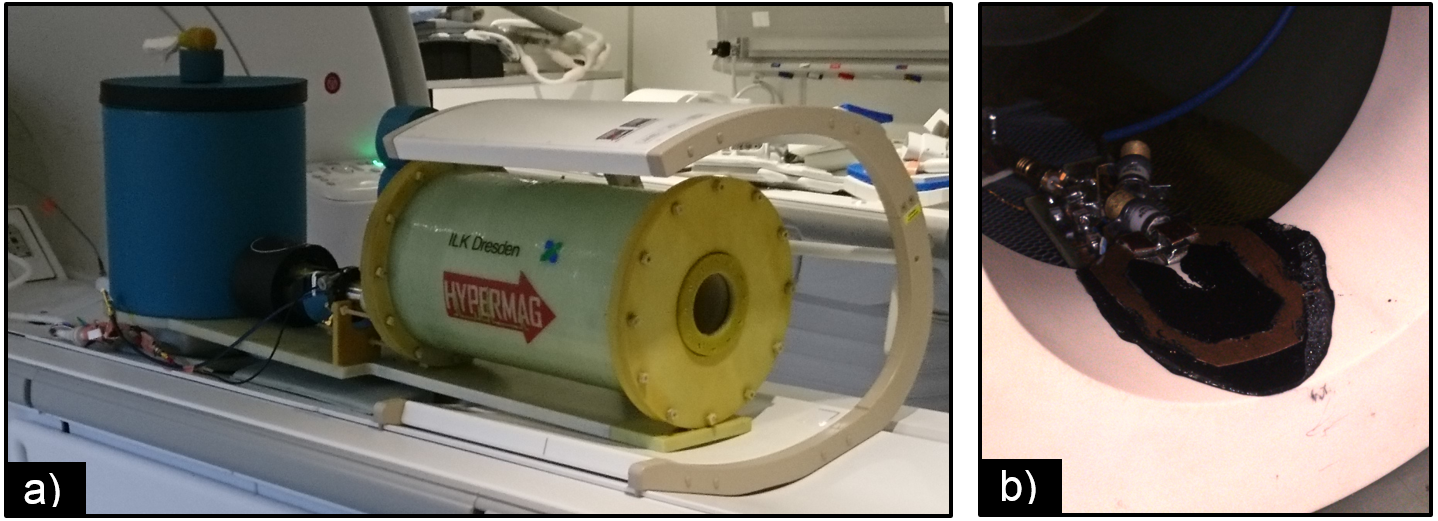
An MRI-transparent cryostat (Fig. 1a) made of fiberglass is used to cool a 30x40 mm copper RF coil (Fig. 1b) and the preamplifier (WMA32C, WantCom, Chanhassen, USA) with LN2, using a vacuum jacket to provide thermal insulation as described in3. Molecular sieves (activated charcoal, and sodium aluminum silicate) are added inside the vacuum chamber, and in contact with the cold walls to improve the vacuum performance. The cooling procedure of the cryostat was done in steps as follows:
1- Cryostat pressure evacuation below 10-3 mbar (prior to cooling).
2- Start of the cooling process: filling of the cooling circuit with 6 L of LN2.
3- Cooling period: after 45 min, the cryostat can be disconnected from the vacuum pump.
4- The cryogenic RF coil is now cold and stable.
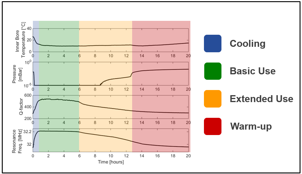
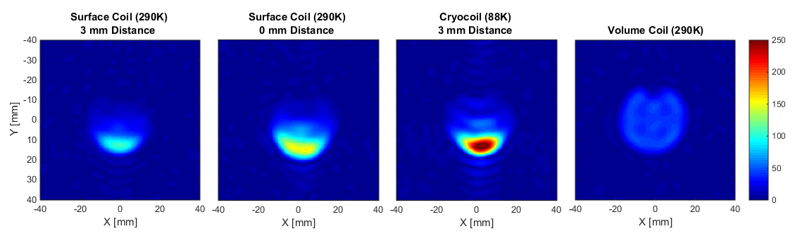
In order to characterize the operational performance of the cryogenic coil, several parameters were monitored during a whole usage cycle of 20 h (temperature at the sample position, cryostat pressure, coil Q-factor, and resonance frequency). Using the same cooling procedure described above, MR experiments were performed on a spherical (38 mm diameter) 13C-enriched bicarbonate. A CSI sequence (16x16 acquired points, TR=75ms, FOV= 80 mm x 80 mm x 10 mm) was used, and the SNR was measured and compared to an identical surface coil at room temperature. Two measurements with the room temperature surface coil were made: one with a coil-to-sample distance of 3 mm (to replicate the setup of the cryocoil), and one with a coil-to-sample distance of 0 mm (to replicate a real-use condition). Finally, a measurement using a volume birdcage coil was done as reference, in order to determine what is the maximum depth where the use of the cryogenic surface coil is beneficial.
Results and Discussion
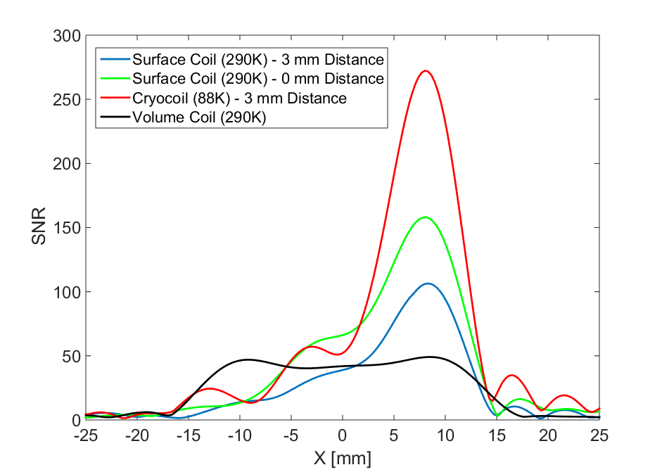
The measured thermal performance of the cryostat and electrical performance of the cryocoil are shown in Fig. 2, over a whole use cycle (up to 20 h). The SNR obtained with the cryocoil is shown in Fig. 3 and compared to the reference cases described above. Finally the SNR across the center axis of the phantom is shown in Fig. 4. The measured results show that after 45 min of cooling the cryogenic coil reaches a stable usable regime in terms of Q-factor and resonance frequency with only minimal variations for the next 5 h. The pressure remains below 10-3 mbar (threshold for thermal insulation) up to 12 hours after the beginning of cooling, providing a relatively warm temperature at the sample position (over 10° C). This shows the good performance of the molecular sieves to keep vacuum low, when the whole setup is not connected to a vacuum pump (as it is the case during MR scanning). The temperature at the animal position can be easily increased to room temperature, by flowing warm (50° C) air through the bore, as it is done routinely in any case for in-vivo experiments3.Conclusion
Cryogenic surface coils can provide a significant SNR
improvement for 13C MRI at 3T of small animals. A cryogenic copper
coil setup is reported with a coil-to-sample distance of 3 mm, which can
provide a 2-fold SNR improvement compared to a similar coil at room temperature
(coil-to-sample of 0 mm). We report excellent thermal stability of the coil for
5 h (for 6 L of LN2), which can be extended up to 12 h by adding more LN2.
This result opens the possibility of developing highly sensitive cryogenic RF
coil arrays for small animal 13C MRI.Acknowledgements
No acknowledgement found.References
1. J. Ginefri, M. Poirier-quinot, O. Girard, and L. Darrasse, “Technical aspects : Development , manufacture and installation of a cryo-cooled HTS coil system for high-resolution in-vivo imaging of the mouse at 1.5 T,” Methods, vol. 43, pp. 54–67, 2007.
2. J. Wosik, L. Xue, L.-M. Xie, M. R. Kamel, K. Nesteruk, and J. A. Bankson, “Superconducting array for high-field magnetic resonance imaging,” Appl. Phys. Lett., vol. 91, no. 18, p. 183503, Oct. 2007.
3. J. D. Sanchez-Heredia, “3-Fold SNR Enhancement of Small Animal 13C MRI using a Cryogenically Cooled (88 K) RF Coil,” ISMRM 2018 Annu. Meet. Exhib., 2018.
Figures