0432
Split-Ring-Resonator shield improves SAR efficiency and homogeneity of birdcage antenna.1Center of Image Sciences, University Medical Center Utrecht, Utrecht, Netherlands, 2ITMO University, St. Petersburg, Russian Federation, 3Biomedical Engineering, Eindhoven University of Technology, Eindhoven, Netherlands
Synopsis
A Split-Ring-Shield is a metamaterial structure that operates as a magnetic shield and thereby increases the penetration of the B1-field of a dipole antenna into a phantom. However, due to increased sample resistance it cannot be used effectively with a conventional birdcage. As a solution, a multi-transmit birdcage coil is presented, which can be used with the SRS. Simulations indicate a 10% increase in SAR-efficiency compared to a conventional birdcage. This setup was constructed and preliminary images were obtained.
INTRODUCTION
Eddy currents in the shield of a birdcage coil partially cancel the coil’s field. This reduces sample resistance, reducing the power needed to generate current. However, this increases the current required to generate the B1+-field, yielding high SAR-levels close to the coil and decreased B1+-homogeneity. To overcome these problems a magnetic shield, with in-phase mirror-currents, has been suggested[1]. This results in lower current per unit B1+, yielding lower SAR-levels and improved homogeneity. Magnetic conductors do not exist, but metamaterials such as a Split-Ring-Shield [1] (SRS) can be designed to exhibit extraordinary electromagnetic properties, such as magnetic conductivity[2,3]. In this work a SRS was designed to behave as a magnetic shield at the Larmor frequency. By applying the SRS to a birdcage, we aim to improve SAR efficiency and B1+-homogeneity.METHODS
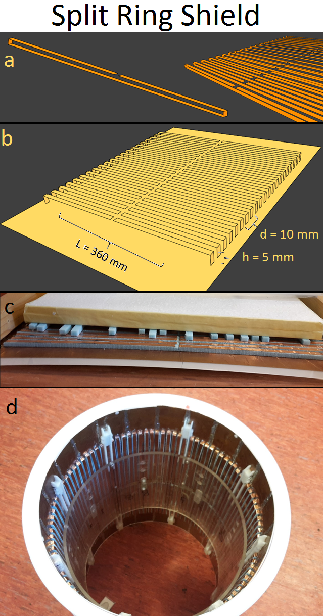
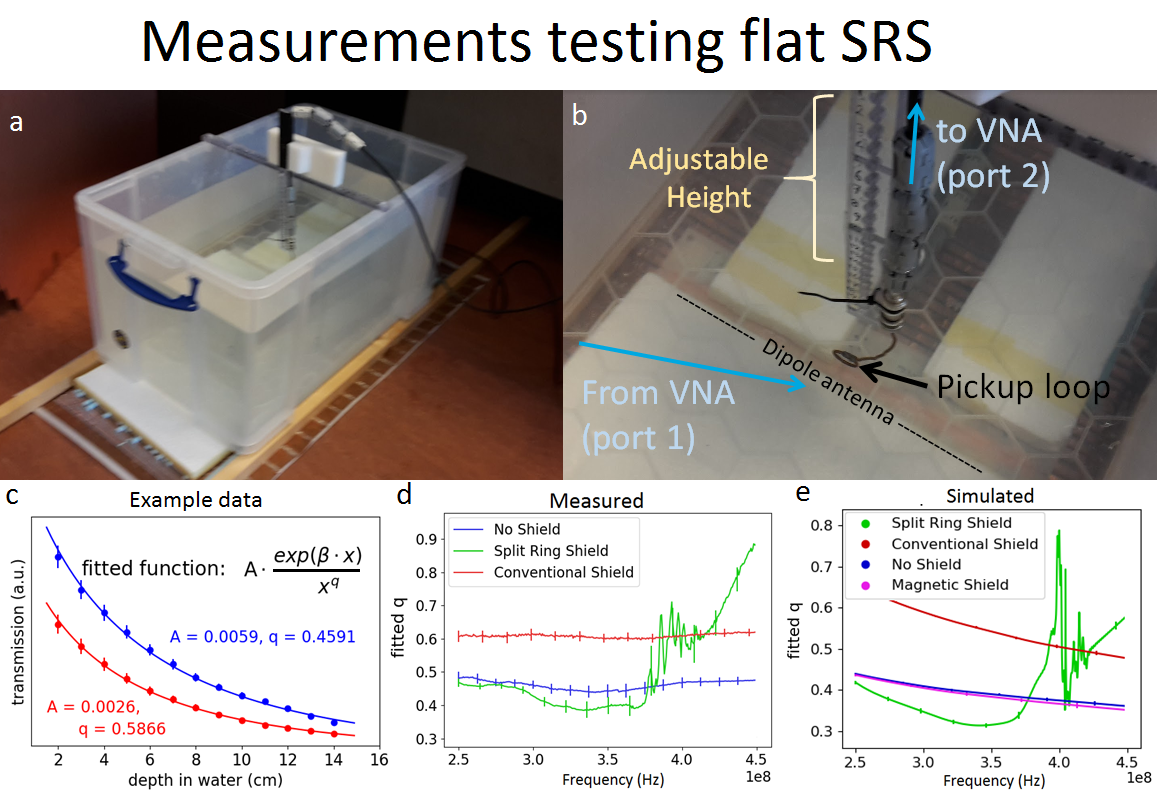
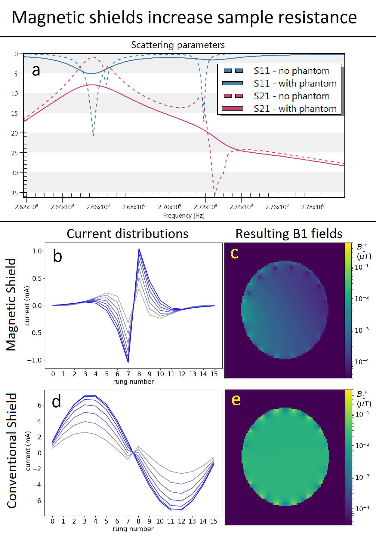
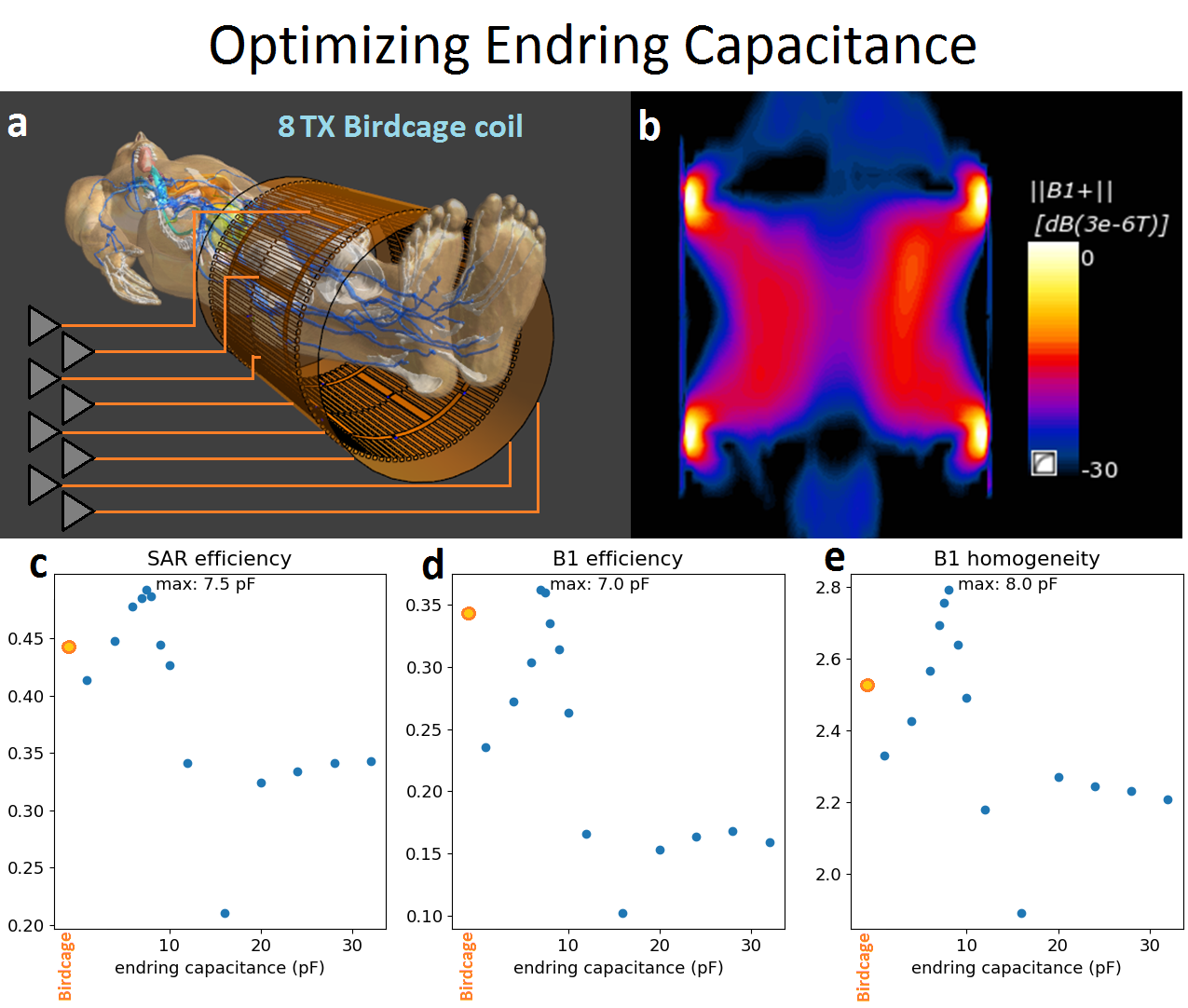
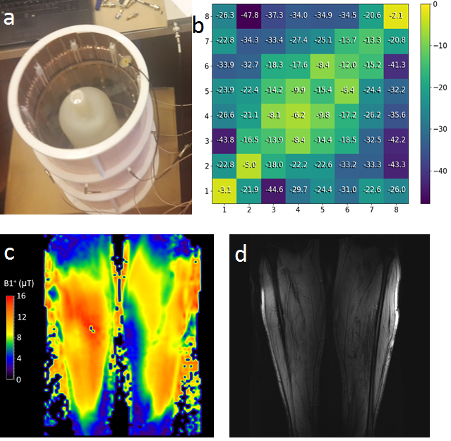
Figure 1 describes the SRS design. The SRS was built by applying copper tape to a plate of Polyoxymethylene, creating a flexible copper back plate. The split-rings were created by applying 6mm wide copper tape to foam spacers, and soldered to the back plate. Finally the shield was curved into cylindrical shape, as depicted in figure 1d. For the flat shield, the reflective properties were measured (figure 2). Penetration of the dipole field into a phantom was measured along a line perpendicularly away from the dipole. A pickup-loop was positioned in the phantom at 15 depth levels with 1cm intervals. S12 was measured and corrected for reflections. A decaying function was fitted to the data to determine the decay rate parameters. These were subsequently compared to simulated data. Figure 3 shows that a magnetic shield (and therefore also the SRS) compromises the operation mode of a birdcage coil. The in-phase mirror currents make the rungs generate stronger fields per unit current, which effectively increases the sample resistance. The resulting low Q-factor (<1, no resonance) makes it impossible to set up the homogeneous mode in the conventional way. For this reason, an eight-channel multi-transmit birdcage was designed with a port in each rung , enabling quadrature excitation using parallel transmission. To make sure the currents in the endrings contribute maximally to the B1+-field this setup was simulated with different values for the endring-capacitors. The optimal value was determined by evaluating SAR-efficiency, B1+-efficiency and homogeneity using FDTD-simulations (Sim4Life, Zurich MedTech, Switzerland) with a realistic human model (“Duke”, ITIS foundation[4]) positioned inside the birdcage (figure 4a). Birdcage dimensions were chosen to function as a scale model at 7T for a 3T body coil and the lower legs were considered a representative imaging target. The multi-transmit birdcage coil was created by positioning a PCB halfway in each leg. A MCX-connector was mounted on the PBCs, along with a matching circuit. Holes (Ø 8mm) were drilled in the SRS to allow coax cables to be connected (fig 1d). Maximum inter-port coupling was only -8.1 dB, caused by the increased loading due to the SRS. The coil was tested in a 7T Achieva system (Philips Healthcare, Best, The Netherlands) and scans were obtained from a healthy volunteer (informed consent). After phase shimming, the B1+-field was mapped using DREAM[5] and gradient echo images were acquired.RESULTS
Figure 2d and 2e show that an antenna with SRS achieves similar decay as an antenna with a magnetic shield over a wide bandwidth. These results show that the SRS indeed operates as a magnetic shield. Figure 4 shows simulation results using a 8TX-birdcage with SRS and realistic human model. Figures 4c,d,e show an endring capacitance of 7.5 pF yields the optimal field distribution, which is shown in figure 4b. This field distribution gives 10% increased SAR-efficiency and increased homogeneity at similar B1+-efficiency, when compared to a conventional 2-port birdcage. Figure 5a shows the realized 8TX-birdcage coil with SRS, figure 5b shows the scattering matrix while 5c and d show the B1+ map and a coronal gradient echo image. Although matching is yet suboptimal, the B1+ field strength is 8-16 μT with 8x800 W forward power. In addition, the field of view in the longitudinal direction is surprisingly large.DISCUSSION & CONCLUSION
We have demonstrated that the Split-Ring-Shield operates as a magnetic shield which increases the penetration of the B1-field of a dipole antenna into a phantom. However, due to increased sample resistance it cannot be used effectively with a conventional birdcage. As a solution, a multi-transmit birdcage coil is presented, which can be used with the SRS. Preliminary imaging results have been obtained showing good transmit efficiency and large field of view. Further improvements are expected by optimizing end-ring capacitance and matching circuits.Acknowledgements
This project has received funding from the European Union's Horizon 2020 research and innovation programme under grant agreement No. 736937References
[1] Van Leeuwen, C.C. et al.,(2017) Improved Performance of Birdcage Coils using a Split-Ring resonator magnetic shield. Proceedings of ISMRM 2018, Paris, abstract ID: 8340
[2] J. B. Pendry et al., Magnetism from Conductors and Enhanced Nonlinear Phenomena, IEEE TRANSACTIONS ON MICROWAVE THEORY AND TECHNIQUES, VOL. 47, NO. 11, NOVEMBER 1999
[3] Koray Aydin et al., Investigation of magnetic resonances for different split-ring resonator parameters and designs, 2005 New J. Phys. 7 168
[4] Gosselin M C, Neufeld E, Moser H, Huber E, Farcito S, Gerber L, Jedensjö M, Hilber I, Di Gennaro F, Lloyd B, Cherubini E, Szczerba D, Kainz W, Kuster N, Development of a new generation of high-resolution anatomical models for medical device evaluation: the Virtual Population 3.0, Physics in Medicine and Biology, 59(18):5287-5303, 2014.
[5] Nehrke, Börnert (2012) DREAM—a novel approach for robust, ultrafast, multislice B1 mapping. Magnetic Resonance in Medicine 68:1517–1526 (2012)
[6] Novikov A. (2011) Advanced theory of driven birdcage resonator with losses for biomedical magnetic resonance imaging and spectroscopy. Magn Reson Imaging. 2011 Feb; 29(2): 260–271.
Figures