0431
Design and implementation of a combined sodium-loop proton-dipole transceiver array for body imaging at 10.5 Tesla1Center for Magnetic Resonance Research, University of Minnesota, Minneapolis, MN, United States, 2Restorative Therapies Group, Medtronic, Minneapolis, MN, United States
Synopsis
A multinuclear combined sodium-proton transceiver array consisting of 8 proton-dipoles and 8 sodium-loops for imaging the body at 10.5T was designed and implemented. Performance of the array was compared against 3 other designs using numerical simulations with the goal of achieving multinuclear imaging capabilities while minimizing the losses typically associated with such dual-tuned coils. The first 10.5T sodium images were obtained inside a saline-filled torso-size phantom with the implemented coil.
Purpose
The goal of this work was to design and build a combined proton/sodium transceiver array for human body imaging at 10.5T, evaluate its transmit and receive performance, and perform proof-of-concept imaging studies. This work is motivated by the desire to provide proton imaging for body applications while simultaneously taking advantage of the expected increases in SNR afforded by 10.5T for sodium where limitations in sensitivity still limit its in vivo utility.Methods
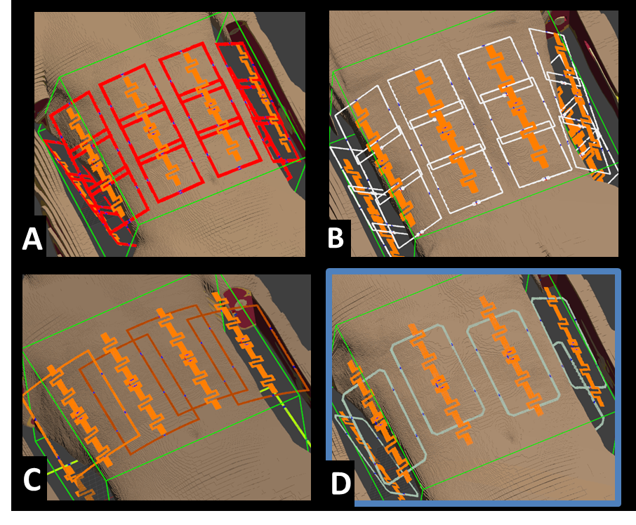
Multiple multinuclear sodium/proton transceiver arrays for body imaging at 10.5T were designed and modeled using Sim4Life software (ZMT, Zurich, Switzerland) positioned around the torso of the Virtual Population Duke model [1]. Sodium and proton frequencies at 10.5T are 118.25 and 447.06 MHz, respectively. Four design concepts (Figure 1, Concepts A-D) were evaluated in terms of their B1+ efficiency and field uniformity (coefficient of variation (CoV) metric) inside the kidneys, peak 10g-averaged SAR, and SNR. In each design, a constant dipole antenna element [2] was employed as the resonant structure for proton while the layout for the sodium channels were varied.
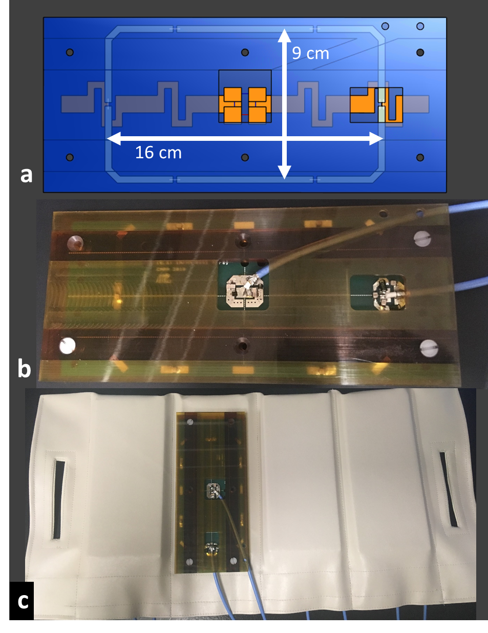
The most promising design consisted of eight fractionated dipole antennas [2] for proton and eight 9x16cm2 loops for sodium imaging. The sodium loops were aligned with proton dipoles to minimize coupling [3]. Loop-dipole elements were implemented using two-sided PCBs, where the dipoles were printed on the load-facing side and loops printed on the side facing away from the load (Figure 2). Four loop-dipole blocks are placed anteriorly and remaining four blocks are placed posteriorly inside a flexible vinyl fabric housing. All sixteen elements were used as transceivers (eight dipole proton and eight loop sodium transceiver channels). Decoupling performance achieved by geometric placement of elements was satisfactory, obviating the need for additional decoupling elements/circuits.
Imaging studies were performed using a torso-sized saline-filled phantom with a concentration of 70mM sodium. Three vials of de-ionized water, two of which contained 140mM sodium and the third one with no sodium were placed at the center of the phantom. In the current system configuration, it was necessary to drive the sodium elements with a single 8kW broadband amplifier and the proton through separate single channel transmit path providing 16 kW of available power. The single proton and x-nuclei transmit channels each passed through high-power narrowband 8-way RF combiner/dividers (Werlatone, NY, USA) providing incremental phase steps of 45 degrees between adjacent elements. Each transceiver element was managed by a nuclei-specific T/R switch.
Results
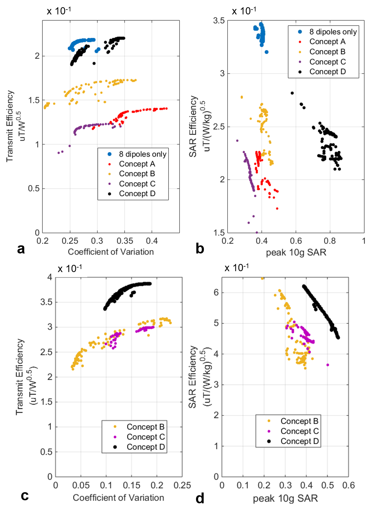
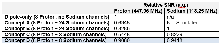
Identical dipole antenna elements are used for proton imaging [2] in all design concepts. Number, size and positioning of Sodium loop elements were varied between four design concepts (Figure 1: 24 loops in Concepts A-B, 8 loops in Concepts C-D). Proton transmit performance of the four array concepts are plotted in Figure 3,a-b: B1+ efficiency vs. CoV and B1+/SAR efficiency vs. peak SAR. Sodium transmit performance are also shown in Figure 3,c-d. Relative proton and sodium SNR of design concepts are provided in Table 1. Concept D was chosen due to its high proton B1+ efficiency and SNR, good sodium SNR (~5% less than Concept B) and easier practical implementation compared to other concepts.
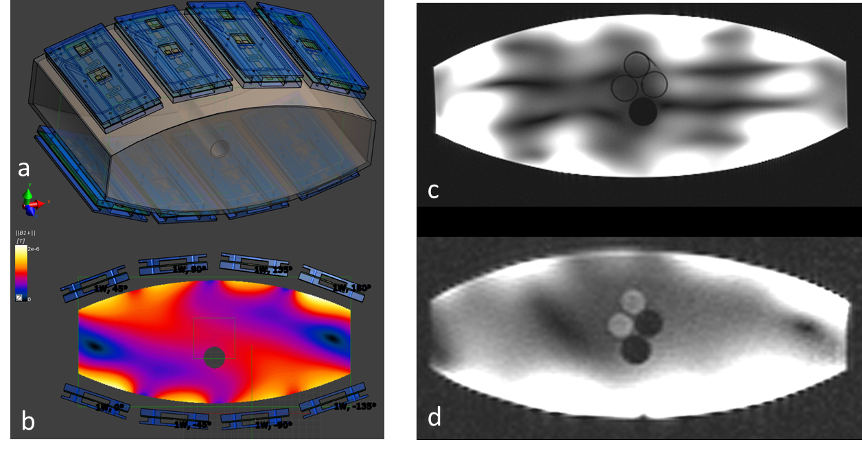
Model of the saline phantom imaging setup and B1+ distribution at sodium frequency with ideal 45° phase difference between neighboring channels are shown in Figure 4,a-b. Axial proton and sodium images inside the phantom are shown Figure 4,c-d. Third vial with no sodium content appears hypointense in Figure 4,d.
Discussion/Conclusion
We compared four combined loop-dipole proton-sodium transceiver array design concepts for human torso imaging at 10.5T through simulations. Then we implemented a 10.5T multinuclear (proton/sodium) body imaging array based on the most promising design concept and acquired the first 10.5T sodium images in phantoms. Next steps include, improving the transmit performance limitations imposed by the fixed relative phases, validating the array for human use and imaging volunteers at 10.5T. Further improvements, including carefully designed and implemented higher channel count arrays on the receive side have the potential to improve SNR and parallel imaging performance further [5-8].Acknowledgements
Supported by: NCI R01 CA155268, NIBIB P41 EB015894, NIH S10 RR029672.References
- Gosselin et al . Phys Med Biol 2014;59/18:5287-5303.
- Ertürk MA et al. MRM 2017;77:434-443.
- Ertürk MA et al. MRM 2017;77:884-894.
- Ertürk MA et al. ISMRM 2017;p1222.
- Shajan G et al. MRM 2016; 75:906-916.
- Van de Bank BL et al. NMR Biomed 2015; 28:1570-1578.
- Mirkes CC et al. MRM 2015; 73:342-351.
- Brown R et al. MRM 2016; 76:1325-1334.
Figures