0430
Toward Human Head Imaging at 10.5T Using an Eight-Channel Transmit/Receive Array of Bumped Fractionated Dipoles1Electrical and Electronics Engineering, Bilkent University, Ankara, Turkey, 2National Magnetic Resonance Research Center (UMRAM), Ankara, Turkey, 3Athinoula A. Martinos Center for Biomedical Imaging, Department of Radiology, Massachusetts General Hospital and Harvard Medical School, Charlestown, MA, United States, 4Center for Magnetic Resonance Research, University of Minnesota, Minneapolis, MN, United States
Synopsis
Introduction
Ultra-High Field (MRI) provides numerous benefits1-3 including increased signal-to-noise ratio4,5. However, increased local specific absorption rate (SAR) is a limiting safety factor for many applications6,7. Therefore, designing transmit arrays (TxArray) that reduce local SAR without impacting overall transmit performance is critical8,9.
Recently, a whole-body 10.5T scanner has been installed in the Center for Magnetic Resonance Research (CMRR) that provides a unique opportunity to investigate human body and brain in detail. Along with other coil designs10-15 a bumped dipole coil array was proposed16 and was demonstrated to have improved SAR performance in simulations.
In this study, we designed and built an eight-channel transmit/receive (T/R) array of bumped fractionated dipoles16 for head imaging at 10.5T. To evaluate RF safety, EM simulations were performed and compared against experimental RF heating and B1+ measurements. Imaging performance was evaluated with a cadaver head imaging study.
Theory and Method
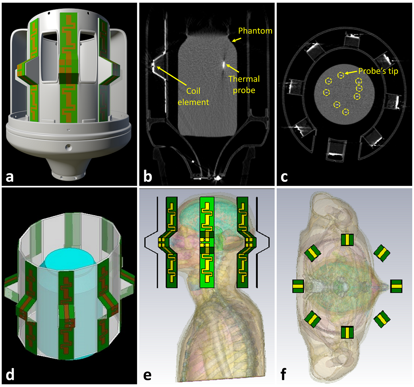
Each element of the array was constructed with an optimal bump height of 30mm at the feed point. The conductors were etched on an RO4003C (Rogers Corp.) laminate and mounted on a 3D printed elliptical holder composed of PETG (Fig. 1a).
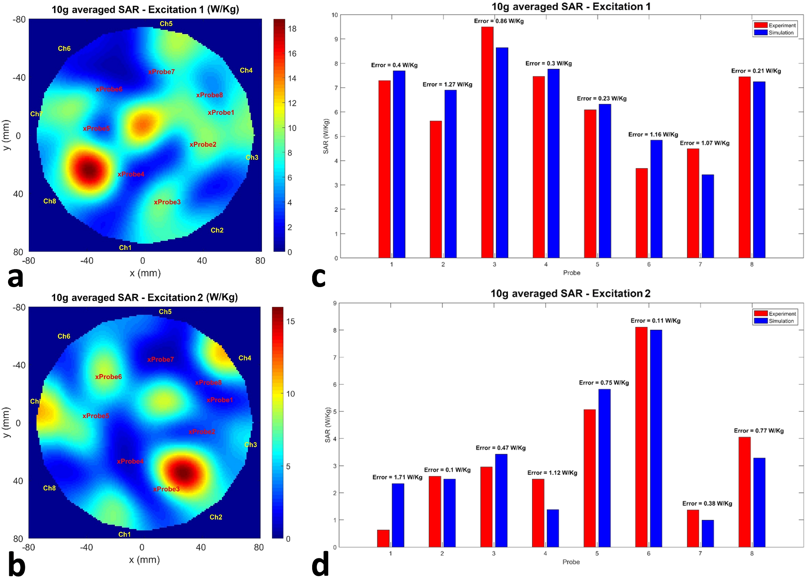
In order to investigate RF safety, a series of RF heating and B1+ mapping experiments were performed using a jar-shaped gel phantom (Radius =75 mm, εr=78.3, σ=0.66 S/m). For the RF heating experiments, the array was excited using eight separate 500 W RF amplifiers (Communications Power Corp., Hauppauge, NY, USA) with arbitrary amplitudes and phases (i.e excitation scenarios 1 and 2). The temperature was measured using eight fiber optic probes (Lumasense Technologies, CA, USA) immersed in the phantom. We calculated the local SAR from the temperature data using the first order approximation. For the B1 measurements, we used actual flip angle imaging17 (AFI).
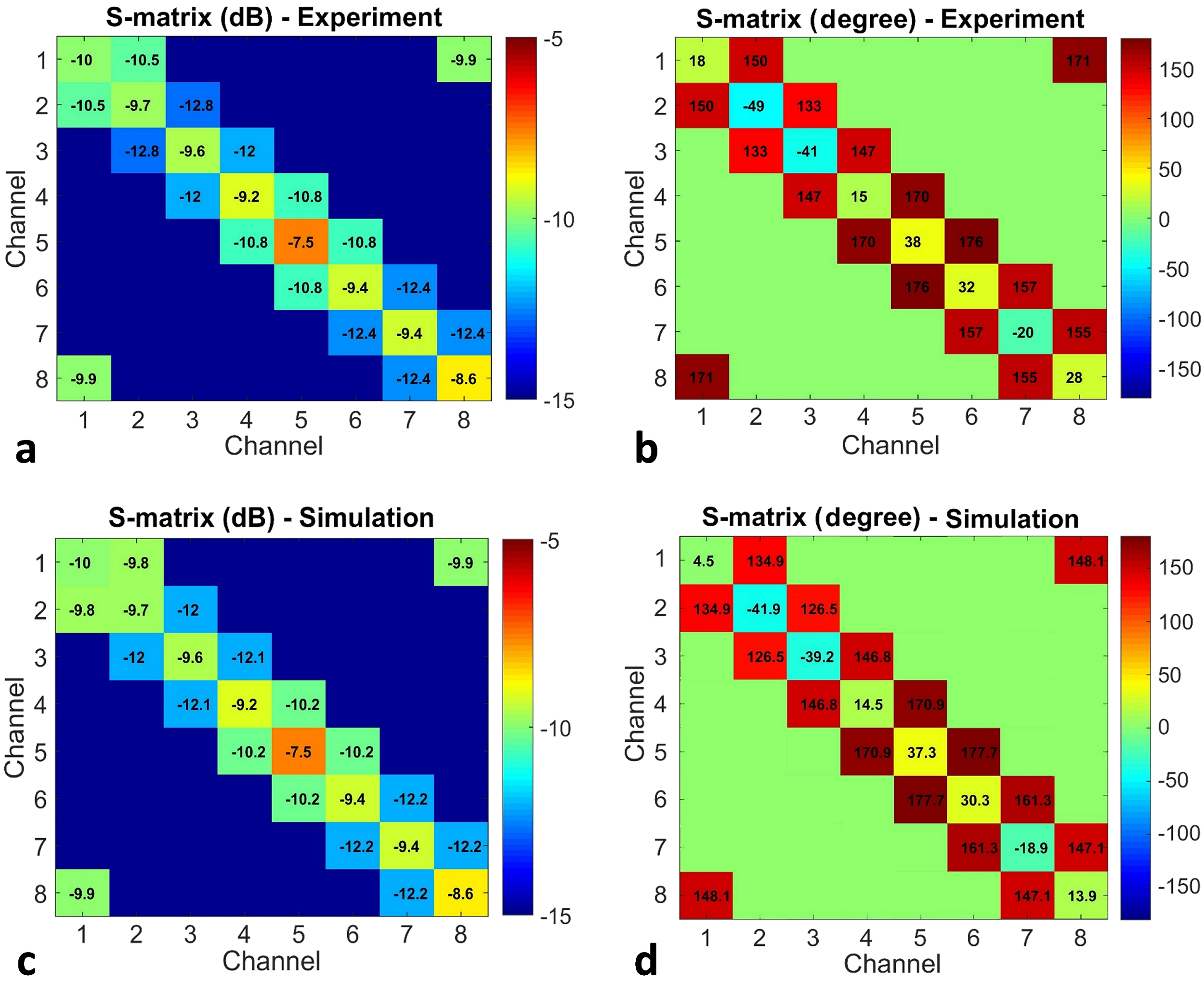
After we completed RF heating and B1 mapping experiments, we measured the scattering (S-) parameters of the array using a sixteen channel vector network analyzer (Rohde & Schwarz ZNBT8, Munich, Germany). Then CT images of the set-up were acquired (Fig 1 b-c) which were later used to model the setup in the simulation environment (HFSS, ANSYS, Canonsburg, PA, USA) as shown in Fig. 1d.
Co-simulation was employed to minimize the difference between the measured and simulated S-matrices. A circuit simulator (AWR Corp., El Segundo, CA, USA) was used for the optimization of the lumped element values. Once a match was achieved with co-simulation, the B1-maps and 10g-averaged SAR were simulated. (Experimental excitation patterns were repeated in the simulations). Finally, the experimental data were compared with EM simulations in order to validate the coil model.
To investigate the peak SAR levels that could be induced in a realistic human head, we performed additional EM simulations. The gel phantom was replaced with the Duke head model18 imported into CST Studio (CST, Darmstadt, Germany), as shown in Fig. 1e-f. As an example, a quadrature excitation was performed.
Finally, we conducted an imaging experiment and acquired 2D turbo spin-echo images of a fixed cadaver head (TR/TE= 5000/72 ms, FOV = 192 × 256 mm2, in-plane resolution = 0.5 mm, slice thickness = 1 mm, and acquisition time = 153 sec) For improved RF uniformity, an RF phase-only shimming solution19 was calculated based on a fast estimation of the multichannel transmit B1 mapping20.
Results
Fig. 2a-b shows the magnitude and phase of the measured S-matrix, while, Fig. 2c-d shows the corresponding S-matrix obtained using the EM simulation after optimizing the lumped elements.
Fig. 3a and 3b show the simulated 10g-averaged SAR-maps corresponding to the excitation 1 and 2. The local SAR values obtained from the simulations and measurements at the locations of the temperature probes’ tips are compared in Fig. 3c and 3d.
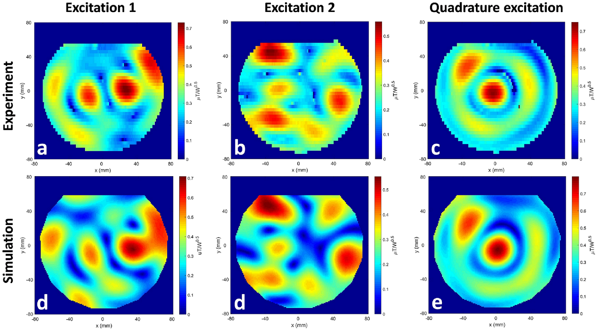
Measured and simulated B1-maps corresponding to the excitation 1, 2 and quadrature excitation are given in Fig. 4.
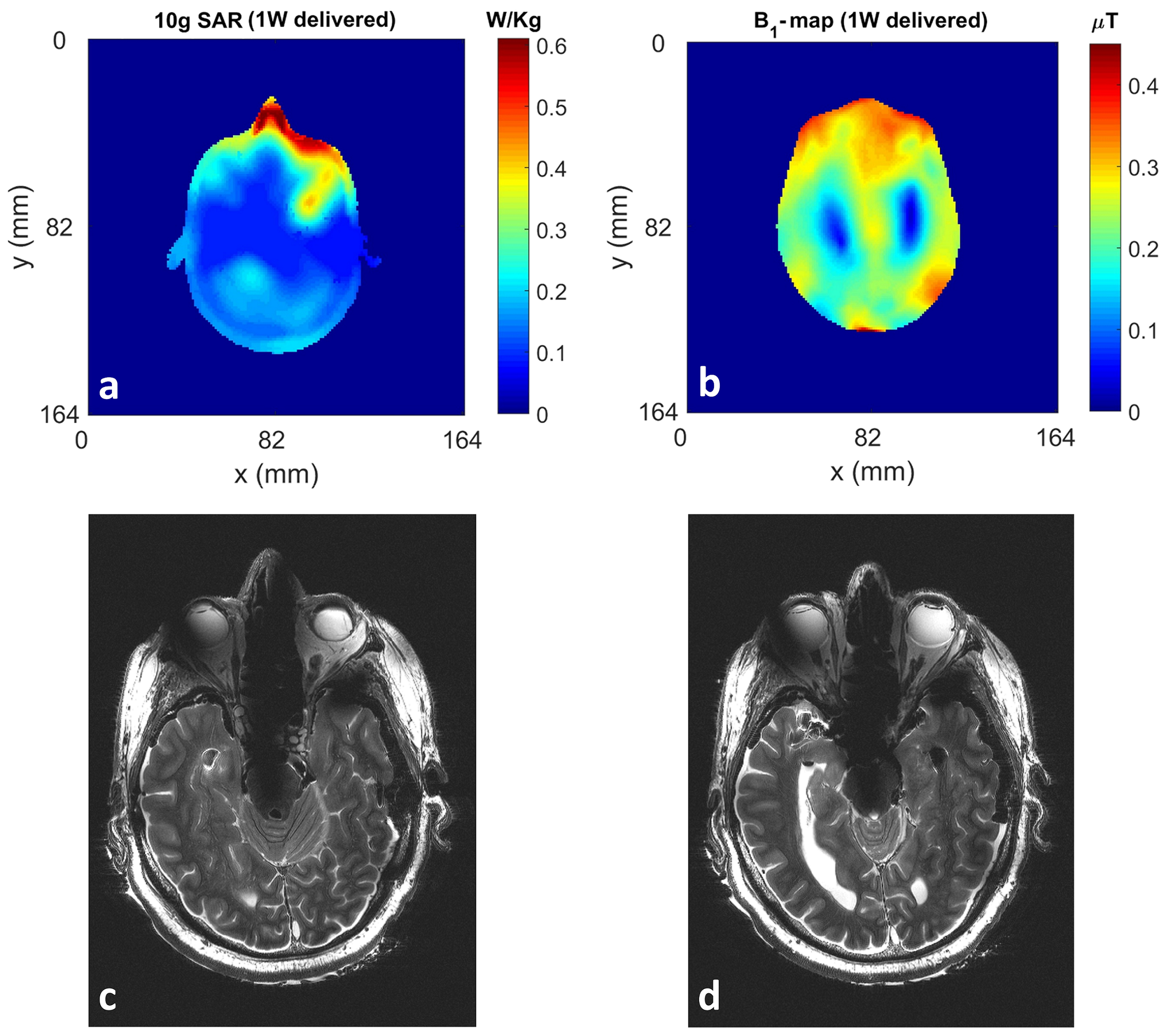
Using the quadrature excitation in the presence of the Duke model, Fig. 5a-b represent the B1- and SAR-maps normalized to 1W delivered power.
Finally, Fig. 5c-d show the cadaver head image at two different transverse slices.
Discussion and Conclusion
We designed and built an eight-channel T/R bumped fractionated dipole array and utilized it for cadaver head imaging at 10.5T. We validated our coil simulation model and established good agreement between the simulation and experimental results. The validated coil model can be used to determine safe power levels for future human head imaging studies. Currently, approval is being sought using the RF safety data presented to obtain FDA approval to use this coil design in vivo.Acknowledgements
This work was supported by following grants: NIBIB P41 EB015894, NIH S10 RR029672, NIH- U01 EB025144.References
1. Cho ZH, Kang CK, Han JY, Kim SH, Kim KN, Hong SM, Park CW, Kim YB. Observation of the lenticulostriate arteries in the human brain in vivo using 7.0 T MR angiography. Stroke. 2008 May 1;39(5):1604-6.
2. Duyn JH, van Gelderen P, Li TQ, de Zwart JA, Koretsky AP, Fukunaga M. High-field MRI of brain cortical substructure based on signal phase. Proceedings of the National Academy of Sciences. 2007 Jul 10;104(28):11796-801.
3. Nakada T, Matsuzawa H, Igarashi H, Fujii Y, Kwee IL. In vivo visualization of senile‐plaque‐like pathology in Alzheimer's disease patients by MR microscopy on a 7T system. Journal of Neuroimaging. 2008 Apr;18(2):125-9.
4. Edelstein, W. A., et al. "The intrinsic signal‐to‐noise ratio in NMR imaging." Magnetic resonance in medicine 3.4 (1986): 604-618.
5. Vaughan T, DelaBarre L, Snyder C, Tian J, Akgun C, Shrivastava D, Liu W, Olson C, Adriany G, Strupp J, Andersen P. 9.4 T human MRI: preliminary results. Magnetic resonance in medicine. 2006 Dec 1;56(6):1274-82.
6. Hoult DI. Sensitivity and power deposition in a high‐field imaging experiment. Journal of Magnetic Resonance Imaging. 2000 Jul;12(1):46-67.
7. Collins CM, Smith MB. Calculations of B1 distribution, SNR, and SAR for a surface coil adjacent to an anatomically‐accurate human body model. Magnetic Resonance in Medicine: An Official Journal of the International Society for Magnetic Resonance in Medicine. 2001 Apr;45(4):692-9.
8. Adriany G, Van de Moortele PF, Wiesinger F, Moeller S, Strupp JP, Andersen P, Snyder C, Zhang X, Chen W, Pruessmann KP, Boesiger P. Transmit and receive transmission line arrays for 7 Tesla parallel imaging. Magnetic Resonance in Medicine: An Official Journal of the International Society for Magnetic Resonance in Medicine. 2005 Feb;53(2):434-45.
9. Metzger GJ, Snyder C, Akgun C, Vaughan T, Ugurbil K, Van de Moortele PF. Local B1+ shimming for prostate imaging with transceiver arrays at 7T based on subject‐dependent transmit phase measurements. Magnetic Resonance in Medicine: An Official Journal of the International Society for Magnetic Resonance in Medicine. 2008 Feb;59(2):396-409.
10. Raaijmakers AJ, Italiaander M, Voogt IJ, Luijten PR, Hoogduin JM, Klomp DW, van Den Berg CA. The fractionated dipole antenna: A new antenna for body imaging at 7 T esla. Magnetic resonance in medicine. 2016 Mar;75(3):1366-74.
11. Thalhammer C, Renz W, Winter L, Hezel F, Rieger J, Pfeiffer H, Graessl A, Seifert F, Hoffmann W, von Knobelsdorff‐Brenkenhoff F, Tkachenko V. Two‐dimensional sixteen channel transmit/receive coil array for cardiac MRI at 7.0 T: design, evaluation, and application. Journal of Magnetic Resonance Imaging. 2012 Oct;36(4):847-57.
12. Ertürk MA, Wu X, Eryaman Y, Van de Moortele PF, Auerbach EJ, Lagore RL, DelaBarre L, Vaughan JT, Uğurbil K, Adriany G, Metzger GJ. Toward imaging the body at 10.5 tesla. Magnetic resonance in medicine. 2017 Jan;77(1):434-43.
13. Alon L, Lattanzi R, Lakshmanan K, Brown R, Deniz CM, Sodickson DK, Collins CM. Transverse slot antennas for high field MRI. Magnetic resonance in medicine. 2018 Sep;80(3):1233-42.
14. Steensma B, Andrade AV, Klomp DW, Van den Berg CA, Luijten PR, Raaijmakers AJ. Body imaging at 7 Tesla with much lower SAR levels: an introduction of the Snake Antenna array. InInternational Society of Magnetic Resonance in Medicine 23rd Annual Meeting & Exhibition 2016 (p. 0395).
15. Chen G, Sodickson D, Wiggins G. 3D curved electric dipole antenna for propagation delay compensation. In Proceedings of the 23nd Annual Meeting of ISMRM, Toronto, Canada, 857 (2015).
16. Sadeghi-Tarakameh A, Torrado-Carvajal A, Ariyurek C, Atalar E, Adriany G, Metzger GJ, Lagore RL, DelaBarre L, Grant A, Van de Moortele PF, Ugurbil K, Eryaman Y. Optimizing the topography of transmit coils for SAR management.
17. Yarnykh VL. Actual flip‐angle imaging in the pulsed steady state: a method for rapid three‐dimensional mapping of the transmitted radiofrequency field. Magnetic Resonance in Medicine: An Official Journal of the International Society for Magnetic Resonance in Medicine. 2007 Jan;57(1):192-200.
18. https://itis.swiss/virtual-population/virtual-population/faq/.
19. Schmitter S, Adriany G, Auerbach EJ, Ugurbil K, Van de Moortele PF. Neither Flat profile nor black spots: a simple method to achieve acceptable cp-like mode transmit b1 pattern for whole brain imaging with transmit arrays at 7 tesla. InProceedings of the 20th Annual Meeting of ISMRM 2012 May 5 (p. 3472).
20. Wu X, Schmitter S, Auerbach EJ, Uğurbil K, Van de Moortele PF. Mitigating transmit B1 inhomogeneity in the liver at 7T using multi-spoke parallel transmit RF pulse design. Quantitative imaging in medicine and surgery. 2014 Feb;4(1):4.
Figures