0276
A Fast and Easy-to-Use Tool for designing High-Permittivity Pads for 3T Body and 7T Neuroimaging Applications1Circuits and Systems Group, Delft University of Technology, Delft, Netherlands, 2C.J. Gorter Center for High-Field MRI, Leiden University Medical Center, Leiden, Netherlands
Synopsis
High-permittivity pads have proved effective for addressing B1+ inhomogeneities for neuroimaging at 7T and body imaging at 3T. In contrast with the ease of constructing these pads, obtaining an appropriate design involves sophisticated and time-consuming electromagnetic field simulations, meaning that in many applications this technique is not fully exploited. We have therefore developed an easy-to-use software tool which can be run on a standard desktop PC to design dielectric pads for 3T body and 7T neuroimaging applications.
Purpose
High-permittivity pads have proved very effective for addressing B1+ inhomogeneities encountered in high field MRI.1–4 Optimal design of these pads is not trivial, however, as typically, a design is obtained through trial-and-error using electromagnetic (EM) field solvers, which results in a highly time-consuming procedure, in sharp contrast to the ease of actually constructing these pads.5 In previous work,6 we have improved the design procedure using reduced order modeling techniques and an optimization scheme. However, these advanced methods require extensive EM and computational resources, meaning that in many applications the use of dielectric shimming materials has not yet been fully exploited. Therefore, in the current work, we present an easy-to-use software tool that allows clinicians and researchers to design dielectric pads for 3T body and 7T neuroimaging applications on a standard desktop PC.Methods
Models
The 7T neuroimaging configuration uses a 15 cm radius high-pass birdcage head coil tuned to 298 MHz. The body model “Duke” from the IT’IS foundation is incorporated on an isotropic grid with a spatial resolution of 5 mm.7 The pad-design domain is defined as a 1 cm thick layer surrounding the head. For the 3T body imaging setup a 128 MHz tuned high-pass birdcage body coil is used, loaded with the same body model “Duke” and discretized on a 7.5 mm isotropic grid. The pad-design domain is defined as a 1.5 cm thick layer around the torso. The body model can be shifted within the birdcage to center different imaging landmarks.
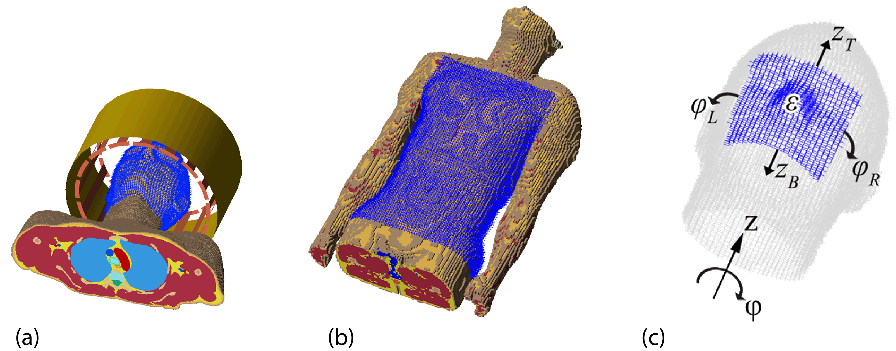
The dielectric pads can be modeled efficiently using diakoptic methods as outlined in previous work.6 To this end, the dynamic pad-design domain is separated from the static full computational domain consisting of the heterogeneous body model and the resonant coils. Subsequently, an offline field response library is computed capturing the static components, such that the online phase only involves the relatively small pad-design domain. The pad model is finally parameterized in terms of the pad’s dimensions, location, and constitution. The methods are illustrated in Figure 1.
The optimization procedure allows one either to find the optimal position of an existing pad, or to find the optimal pad’s geometry, position, and composition. For both procedures the B1+ field can be optimized for either the transmit efficiency, homogeneity, or a combination of both.
Design tool
The stand-alone tool was created in MATLAB (R2015a, The MathWorks, Inc., Natick, Massachusetts, USA) and can run on a standard desktop PC or use a GPU if available to accelerate computations. The tool can be downloaded as an executable file at https://paddesigntool.sourceforge.io.
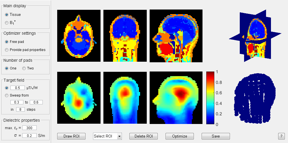
The graphical user interface for the 7T configuration is shown in Figure 2. The interface allows one to define a three-dimensional ROI by drawing two-dimensional ROIs in the three isometric views at the top. A target B1+ amplitude can be set, or alternatively, an optimization sweep over a range of B1+ amplitudes can be carried out to enable a trade-off analysis between transmit efficiency and B1+ homogeneity. All optimizations can be performed for either one or two pads.
Results
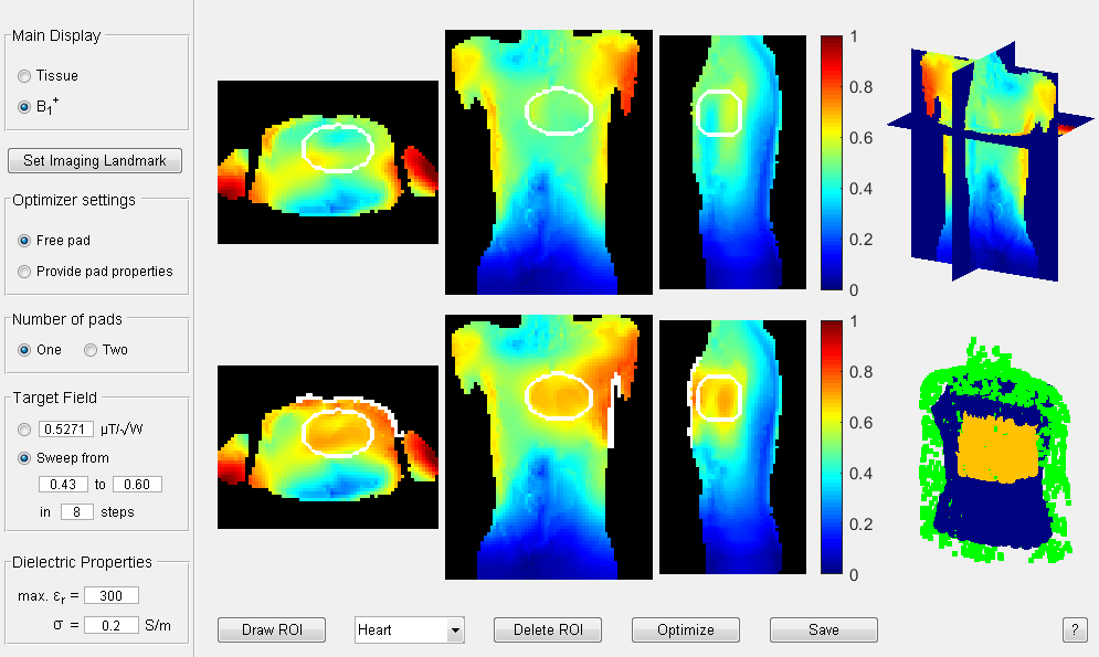
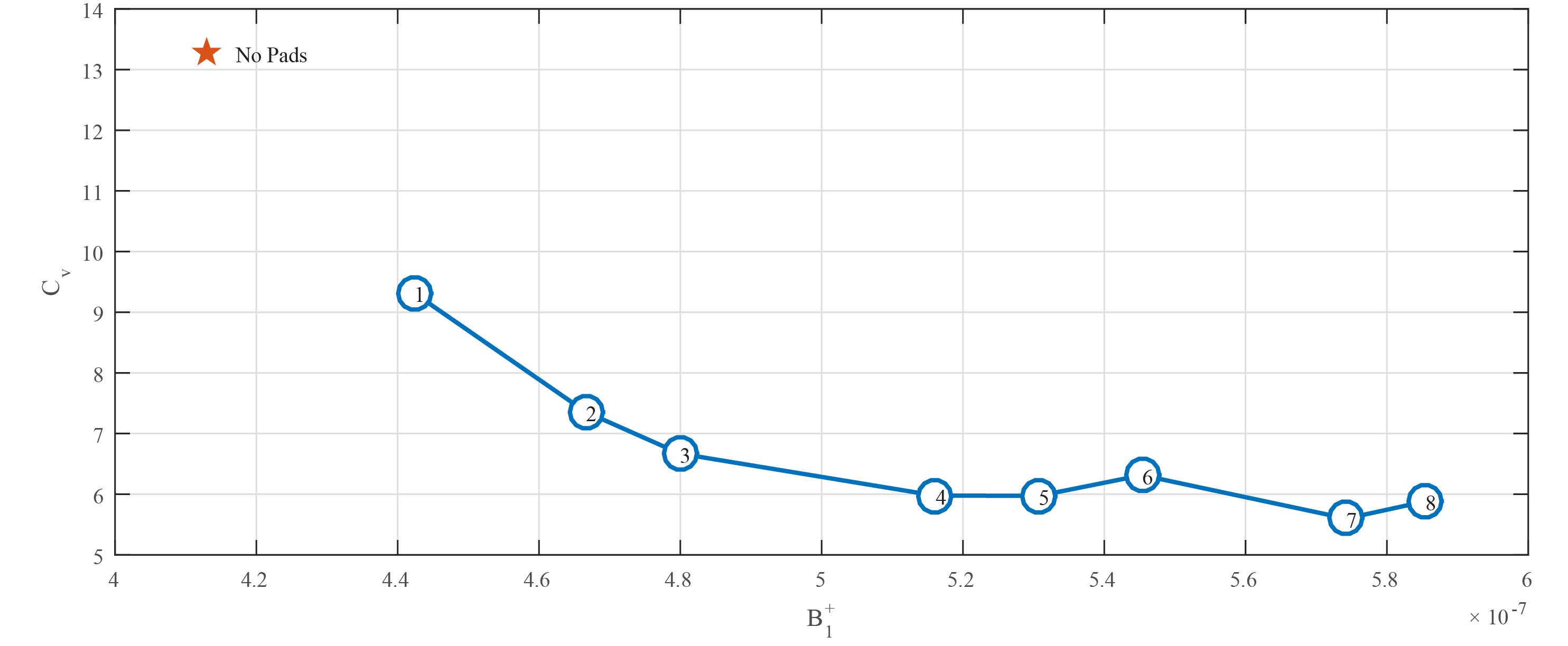
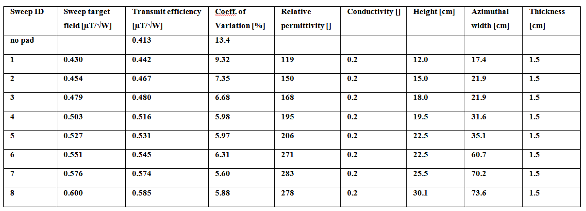
To demonstrate the utility of the tool, we design a single dielectric pad for cardiac imaging at 3T using an Intel Xeon CPU X5660 @ 2.80 GHz (dual core) PC equipped with a NVIDIA Tesla K40c GPU. First, the heart is centered within the birdcage and assigned as the ROI, as shown in Figure 3. We then select the sweep option to perform a trade-off analysis between the transmit efficiency and B1+ homogeneity. Within 2 minutes on the GPU, or less than 8 minutes on the CPU, the results are presented as illustrated in Figure 4 and Table 1. In this case the most practical choice is pad #4 (19.5 x 31.6 x 1.5 cm3 with a relative permittivity of 195 and a conductivity of 0.2 S/m) since it improves both the transmit efficiency as well as homogeneity, and it has practical dimensions: pads #7 and #8 provide marginal improvements in performance but require a much larger pad.Conclusion
We have designed an easy-to-use software tool to design dielectric pads for 7T neuroimaging and 3T body imaging applications. The application can be downloaded and pads can be designed in a couple of minutes. We anticipate this will help to bridge the gap between the advanced numerical design methods and the practical application by the MR community.Acknowledgements
This project was funded by the Dutch Technology Foundation (STW) project 13375 and the European Research Council Advanced Grant 670629 NOMA MRI.References
1. Yang QX, Mao W, Wang J, et al. Manipulation of image intensity distribution at 7.0 T: Passive RF shimming and focusing with dielectric materials. J Magn Reson Imaging. 2006;24(1):197–202.
2. Haines K, Smith NB, Webb AG. New high dielectric constant materials for tailoring the B1+ distribution at high magnetic fields. J Magn Reson. 2010;203(2):323–327.
3. de Heer P, Brink WM, Kooij BJ, Webb AG. Increasing signal homogeneity and image quality in abdominal imaging at 3 T with very high permittivity materials. Magn Reson Med. 2012;68(4):1317–1324.
4. Brink WM, Webb AG. High permittivity pads reduce specific absorption rate, improve B 1 homogeneity, and increase contrast-to-noise ratio for functional cardiac MRI at 3 T. Magn Reson Med. 2014;71(4):1632–1640.
5. O’Reilly TPA, Webb AG, Brink WM. Practical improvements in the design of high permittivity pads for dielectric shimming in neuroimaging at 7 T. J Magn Reson. 2016;270:108–114.
6. van Gemert JHF, Brink WM, Webb AG, Remis RF. High-Permittivity Pad Design for Dielectric Shimming in Magnetic Resonance Imaging Using Projection-Based Model Reduction and a Nonlinear Optimization Scheme. IEEE Trans Med Imaging. 2018;37(4):1035–1044.
7. Christ A, Kainz W, Hahn EG, et al. The Virtual Family—development of surface-based anatomical models of two adults and two children for dosimetric simulations. Phys Med Biol. 2010;55(2):N23–N38.
Figures