0273
Wireless coil as a portable and practical alternative to a dedicated transceive coil for extremities MRI at 1.5T1Department of Nanophotonics and Metamaterials, ITMO University, Saint Petersburg, Russian Federation
Synopsis
We show for the first time that a metamaterial inspired, volumetric wireless coil demonstrates similar performance as the same size, cable-connected volume transceiver coil for extremities MRI at 1.5T. Numerical analysis and in vivo human wrist imaging with the wireless coil showed proper quality images with no
Introduction
Good quality clinical MRI of extremities is conventionally performed with dedicated transceive radiofrequency (RF) coils, i.e., so-called extremity coils (EC). These coils have to be placed directly onto the patient table of an MR system, and their high RF power supply cables are thus close to a patient. The latter can potentially breach the safety of the procedure. Also, these coils are usually relatively heavy and bulky while the presence of fragile elements demands careful handling each time these coils are positioned and dismounted. Recently, a novel alternative, wireless approach has been proposed. The approach is based on the metamaterial inspired wireless coils (WLC)1-3 electromagnetically coupled to the body birdcage coil (BC). Such WLCs can redistribute an electromagnetic field of the BC and focus it in the region of interest. This boosts locally body BC’s MR-relevant characteristics, i.e., transmit efficiency and receive sensitivity. However, for routine clinical application of WLC RF safety4 aspects have to be evaluated and carefully compared to conventional setups. In the present study, we investigated a volumetric WLC3 for wrist imaging at 1.5T and compared it with a Tx/Rx EC.Methods
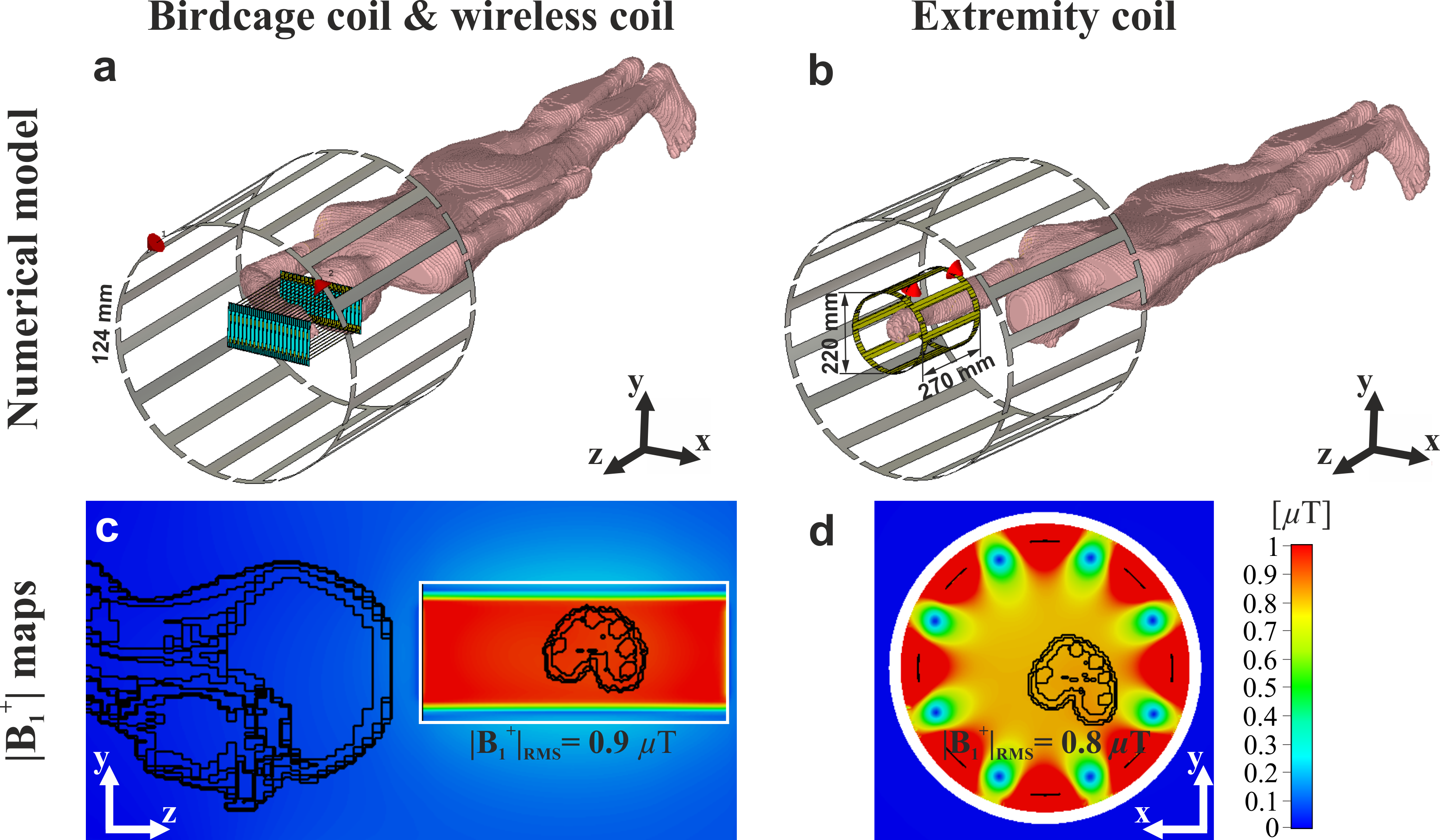
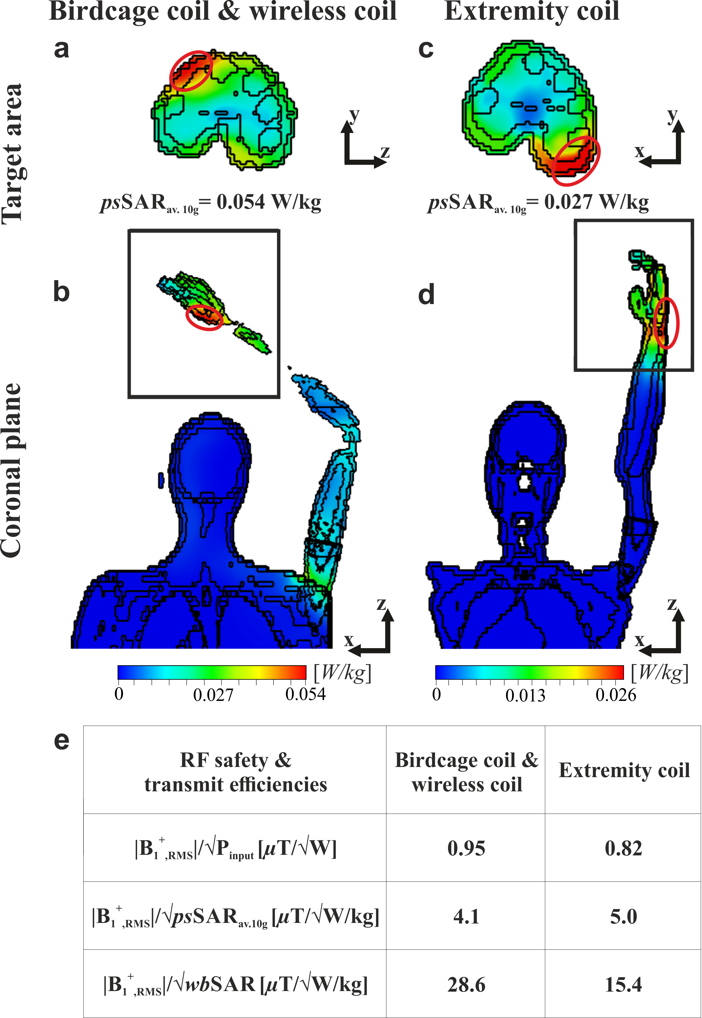
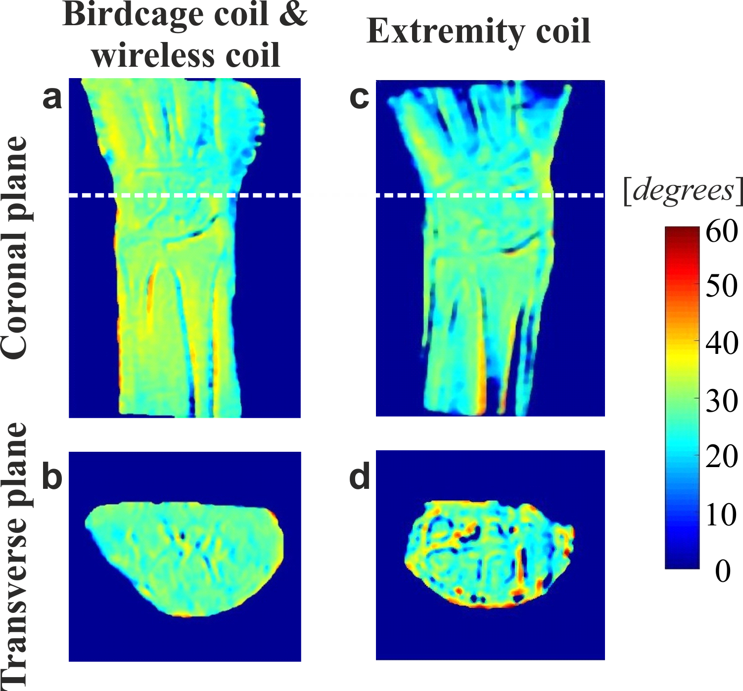
Electromagnetic simulations were done using a voxelized human model in prone position in CST Microwave Studio 2017 for three setups: (1) a standard body BC; (2) a standard body BC in the presence of the WLC and (3) a small BC (its’ size is comparable to the WLC, i.e. EC (Figure 1a-c). The BC was matched without the WLC, so the addition of the WLC led to a parasitic detuning of the BC. The model of the WLC was taken from the previous work3 and tuned to the 63.6 MHz by adjusting the length of the tubes to L=270mm. The B1+-field and SAR distributions were normalized to 1W of the total accepted power. The RF safety aspects were assessed by the following equations: $$$|\textrm{B}_{1,\textrm{RMS}}^+ |/\sqrt{\textrm{psSAR}_\textrm{av.10g}}$$$ and $$$|\textrm{B}_{1,\textrm{RMS}}^+ |/\sqrt{\textrm{wbSAR}}$$$, where $$$|\textrm{B}_{1,\textrm{RMS}}^+|$$$ - the root mean squared value in the area of interest, psSARav.10g – peak spatial SAR value (10g averaged), wbSAR – whole exposed body SAR. In vivo MR images of a healthy volunteer in a prone position with the forearm lying flat on the table above the volunteer’s head were acquired on 1.5T Siemens Magnetom Espree whole-body system. In the presence of the WLC, the BC was used in both Tx/Rx modes, and the RF power was calibrated manually. Reference in vivo images were acquired using a Tx/Rx EC. B1+-mapping using the double flip angle method was performed to confirm the effectiveness of the manual RF power calibration procedure. SNR-maps were based on the SE sequence. A noise level was calculated as standard deviation of pixel values in the images acquired with no RF excitation (i.e. noise-only images).Results
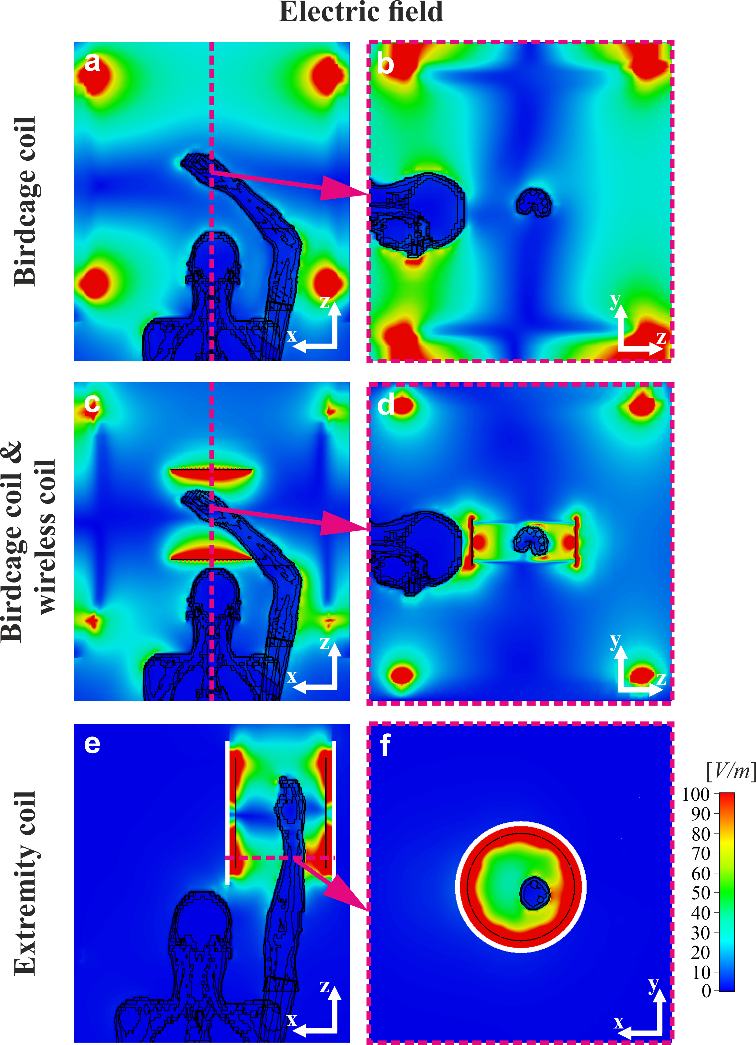
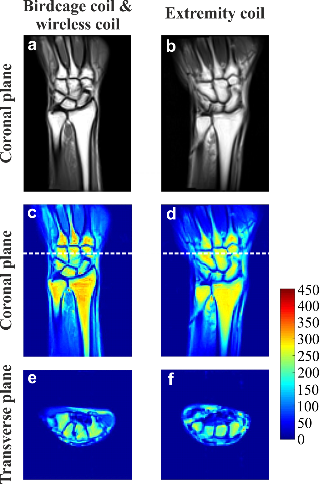
Figure 1 shows numerically calculated $$$|\textrm{B}_{1,\textrm{RMS}}^+|$$$-maps for a voxelized human model placed inside the BC with the WLC and the EC. The B1+ distribution in the area of interest is homogeneous for both cases. Moreover, despite the suboptimal matching condition of the BC’s ports (S11~ -5 dB) when combined with the WLC the resulting transmit efficiency is comparable to a well-matched EC. Figure 2 demonstrates numerically calculated electric field distributions. When the BC is used alone electric field in the wrist area (i.e., imaging area) has negligible amplitude, while the peak spatial SAR values occur near the human head. The WLC redistributes electromagnetic field of the BC and localizes it near the target area similar to the EC. The ratio $$$|\textrm{B}_{1,\textrm{RMS}}^+ |/\sqrt{\textrm{psSAR}_\textrm{av.10g}}$$$ was only 18% lower, while the ratio $$$|\textrm{B}_{1,\textrm{RMS}}^+ |/\sqrt{\textrm{wbSAR}}$$$ was 190% higher for the WLC compared to the EC. Figure 4 shows experimentally obtained flip angle maps for the BC combined with the WLC and for the EC. The measured actual flip angle value agreed in both cases with the nominal flip angle confirming the reliability of the manual transmitter calibration. The calculated SNR-maps (Figure 5) demonstrated that the WLC substantially improved receive performance of the BC making it comparable with the EC.Discussion and conclusions
WLC inductively coupled to the BC can replace the dedicated EC. The benefits of WLC is the absence of RF cables and electronics, little weight (∼1kg) and flexibility of positioning onto the patient table. SAR limits of the EC that are already present in an MR system could be safely adopted when performing an MRI examination with the metamaterial inspired WLC.Acknowledgements
This work was supported by the Russian Science Foundation (Project No. 18-79-10167). The authors thank Dr. Alexander Efimtsev for assistance with MRI experiments.References
1. Slobozhanyuk A P, et al. Enhancement of Magnetic Resonance Imaging with Metasurfaces. Adv. Mater. 2016;28:1832-1838.
2. Shchelokova A, et al. Wireless coil based on meta-technologies for MRI implementations. Proc. Intl. Soc. Mag. Reson. Med. 2017;25,0761.
3. Shchelokova A, et al. Volumetric wireless coil based on periodically coupled split-loop resonators for clinical wrist imaging. Magn Reson Med. 2018;80(4):1726-1737.
4. Murnbach A V et al. Whole-body and local RF absorption in human models as a function of anatomy and position within 1.5T MR body coil. Magn Reson Med. 2014;71(2):839-845.
Figures