0271
High Resolution TRASE by Rapid Echo Encoding with Twisted Solenoid RF Phase Gradient Coils1Department of Onoclogy, University of Alberta, Edmonton, AB, Canada, 2Department of Biomedical Engineering, University of Saskatchewan, Saskatoon, SK, Canada
Synopsis
TRASE is an MRI k-space encoding method that uses radio-frequency transmit phase gradient fields to achieve millimeter-level spatial resolution. To avoid resolution loss, the total echo train duration should be less than 1.2 times T2. However, previously demonstrated TRASE experiments have been limited by a large echo spacing (~1100 us). Here we present the use of the twisted solenoid to achieve short echo spacing of ~370 us, while remaining within SAR limits. This rapid echo encoding will enable in vivo imaging of short T2 tissues (e.g. ~50ms T2 for muscle at 0.2T) with resolution of 1.2 mm per pixel.
Introduction
Transmit Array Spatial Encoding (TRASE) is an alternative MRI method that executes k-space encoding using transmit RF phase gradient fields, instead of conventional B0 gradients. TRASE functions entirely with RF technologies and is suitable for low-field and low-cost MRI systems1. TRASE encoding is based on long echo trains in which later echoes correspond to high spatial frequencies. Consequently, TRASE is vulnerable to resolution loss via k-space filtering, caused by T2 losses down the echo train. Previous studies have demonstrated that TRASE is capable of achieving clinical-level millimeter spatial resolution2-4, but only in long T2 phantoms, due to a long echo spacing (1100 us)3. There is therefore a pressing need to shorten echo train durations (to ~ 1.2T2) by more efficient RF coil designs. Here we report the first images with a new type of phase gradient coil suitable for transverse B0 geometries: a solenoid twisted about a transverse axis5. This new type of coil has many attractive characteristics, including efficient generation of a cylindrical volume of uniform B1 field, large imaging field-of-view (FOV) relative to aperture, single current path, open access for patients, and spatial encoding in any transverse direction (including B0 direction). This design yields much more rapid echo encoding with echo spacing of ~370 us, allowing imaging of short T2 (e.g. muscle of ~50 ms at 0.2T6).Methods
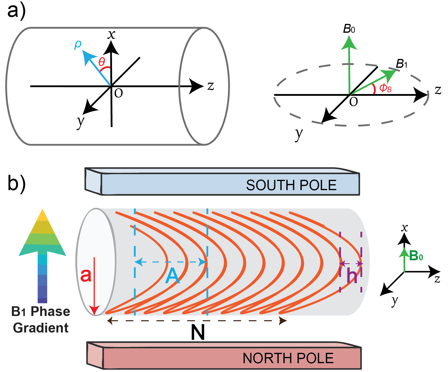
A twisted solenoid coil consists of a single wire path wound on the surface of a cylindrical former, described by the parametric curve 𝑃(𝜃), with 𝑃𝑥(𝜃)=acos(𝜃); 𝑃𝑦 (𝜃)=asin(𝜃); 𝑃𝑧 (𝜃)=Asin(2𝜃)+(h/2π)𝜃, where a, A, and h represent coil turn radius, modulation amplitude, and turn advance (pitch), respectively (illustrated in Fig.1).
To calculate the field within the cylindrical aperture, the continuous current sheet approximation based upon analytical Biot-Savart’s law was used. For a vertical B0 field (x – direction), the contributing transverse B1 components are By and Bz. The B1 field components, magnitude |B1| and phase gradient Gx can be written as7: $$|B_1|=\sqrt{B_y^2+B_z^2}=\mu_0\frac{I}{h}\sqrt{({\frac{Ax}{a^2}})^2+1}$$ $$G_x = \frac{1}{a}\cdot\frac{A/a}{1+(A/a)^2(x/a)^2}$$
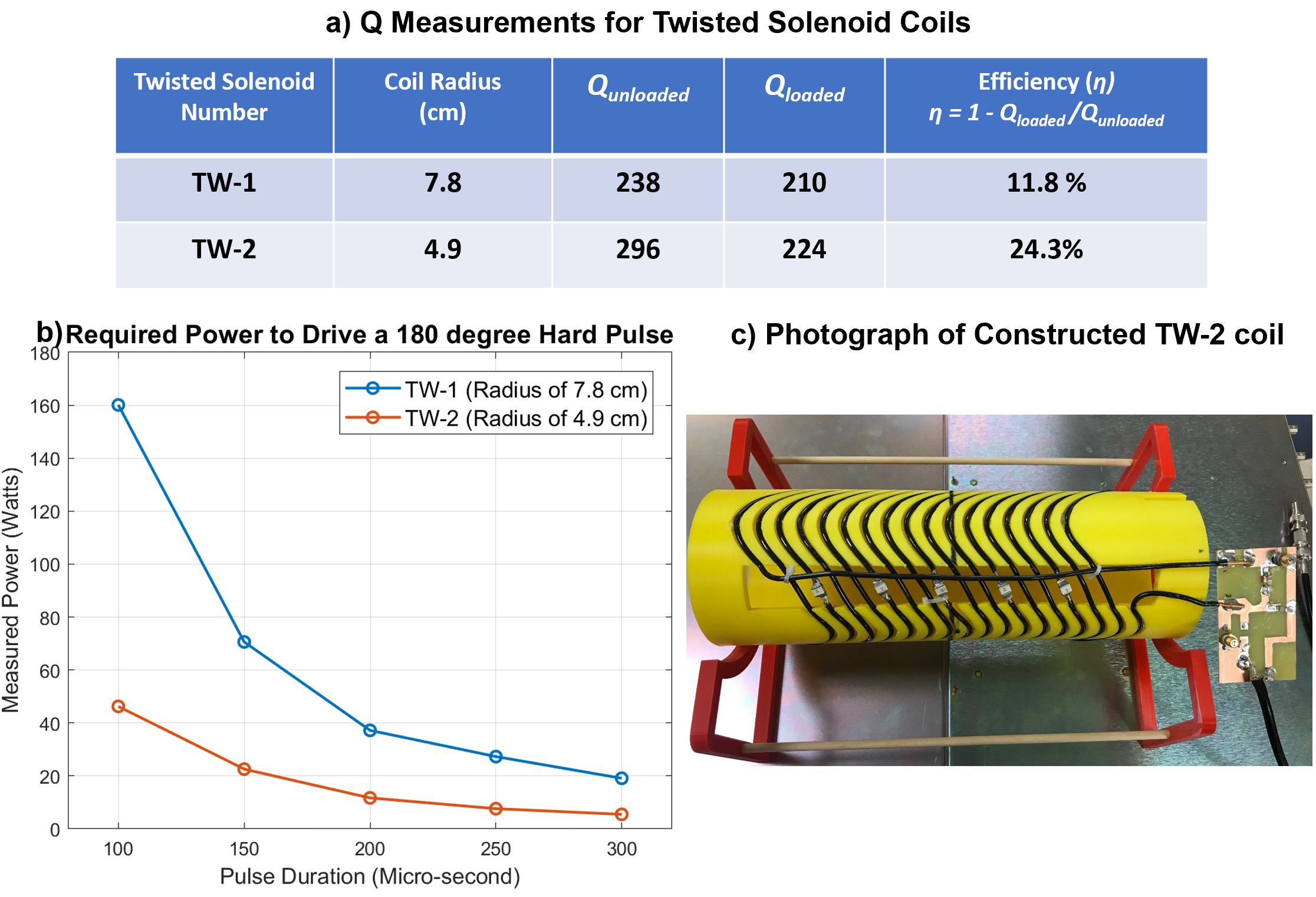
These complex wire patterns were accurately reproduced by 3D printing using PLA (polylactic acid). Two different twisted solenoid coils with radii 7.8 cm and 4.9 cm were constructed. Loaded and unloaded quality factor (Q) measurements were made. RF power (P) required for a 180 degree flip angle of given pulse length was determined from NMR measurement.
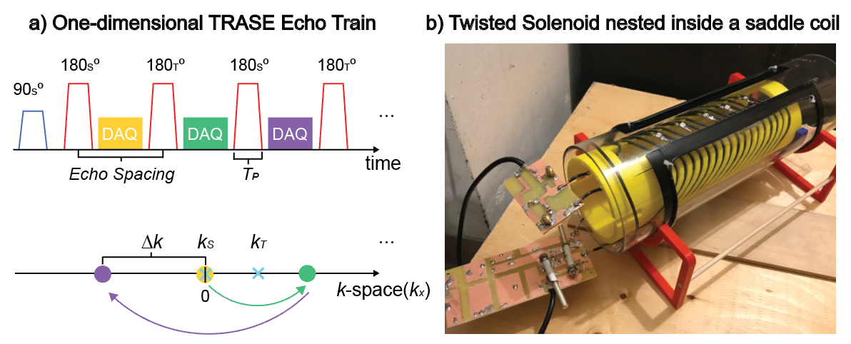
To perform TRASE experiments, an orthogonal saddle coil was constructed, and geometrically decoupled from the twisted solenoid coil under test. 2D MR phantom (multiple doped vials) images were acquired by combining 1D TRASE encoding with 1D B0 phase encoding, using a 0.2T magnet system. A custom-made multi-channel power amplifier system generated high RF duty cycle RF pulses required for the echo trains.
Results
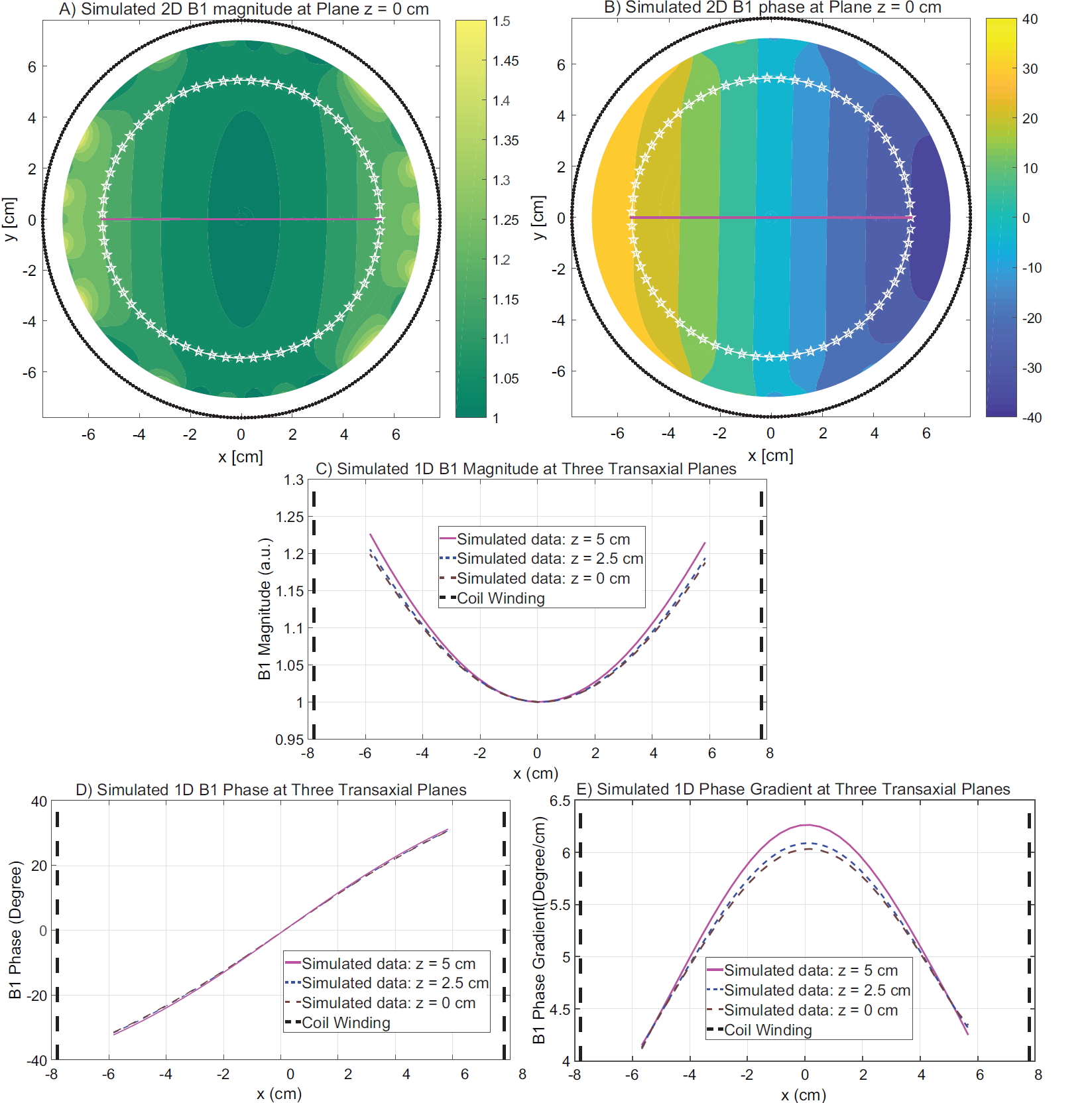
Good agreement on the coil field was found between analytical, Biot-Savart, field plotting and imaging experiments.
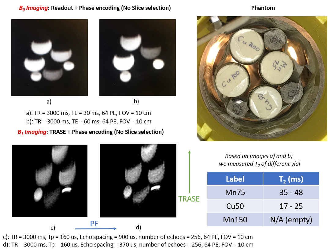
The B1 field plot for a 10-turn twisted solenoid coil (a = 7.8cm, A = 5.5cm, h = 3.0cm) was calculated, and can be found in Fig. 2. The Q and consumed power P were measured and reported in Fig.3. The TRASE pulse diagram is depicted in Fig.4. The multiple-vial phantom and obtained 2D MR images (Conventional B0 imaging vs. TRASE B1 imaging) are shown in Fig.5.
Discussion
In our test, two twisted solenoid coils (radius of 7.8 cm and 4.9 cm) are both functioning well at 100us 180 degree hard pulses, with maximum required power less than 160W. Both twisted coils present similar Q values varying between 200 and 300. TW-2 coil is at smaller size and more efficient, thus, consuming less power (see Fig. 3).
In Fig.5 as expected, samples sitting beyond the design FOV exhibit distortions due to phase gradient non-linearities. However, since the variation of the phase gradient is known, correction technologies such as regularized least squares8 can be applied.
Conclusion
The twisted solenoid coil design is a new type of efficient and compact RF coil for TRASE encoding. It offers an open unobstructed aperture, a large fraction being usable as the imaging volume. The cylindrical outer shape is particularly advantageous for cylindrical Halbach-style permanent magnets.
With this coil design we have demonstrated that short echo spacing (~370us) TRASE sequences can be achieved, capable of imaging short T2 tissues with resolution of ~1.2mm/pixel. At low field TRASE remains within SAR limits (e.g. at 0.2T for a head coil, 2900 200us pulses per second are allowed). Since any transverse phase gradient can be generated by rotating a twisted solenoid coil, multiple coils could be combined to provide high-resolution in-vivo 2D TRASE images.
Acknowledgements
This work is supported by the University of Alberta, Cross Cancer Institute, and Natural Sciences and Engineering Research Council (NSERC). We would like to thank Dr. Vyacheslav Volotovskyy, Dr. Nicola De Zanche, Miss. Stephanie Yong, and Mr. Radim Barta for the valuable comments and advice.References
1. Stockmann, J. P., Cooley, C. Z., Guerin, B., Rosen, M. S., & Wald, L. L. (2016). Transmit Array Spatial Encoding (TRASE) using broadband WURST pulses for RF spatial encoding in inhomogeneous B0 fields. J Magn Reson, 268, 36-48. doi:10.1016/j.jmr.2016.04.005
2. Sharp, J. C., & King, S. B. (2010). MRI using radiofrequency magnetic field phase gradients. Magn Reson Med, 63(1), 151-161. doi:10.1002/mrm.22188
3. Deng, Q., King, S. B., Volotovskyy, V., Tomanek, B., & Sharp, J. C. (2013). B1 transmit phase gradient coil for single-axis TRASE RF encoding. Magn Reson Imaging, 31(6), 891-899. doi:10.1016/j.mri.2013.03.017
4. Sharp, J. C., King, S. B., Deng, Q., Volotovskyy, V., & Tomanek, B. (2013). High-resolution MRI encoding using radiofrequency phase gradients. NMR Biomed, 26(11), 1602-1607. doi:10.1002/nbm.3023
5. B. T. Stephanie Yong, J. C. Sharp (2017). The twisted solenoid RF phase gradient transmit coil for TRASE imaging, Proc. Intl. Soc. Mag. Reson. Med. 25 Honolulu, p. 4281
6. Takamori, Masayoshi & Akiyama, Sumikazu & Yoshida, Kazuya & Imaizumi-Ohashi, Yoshie & Yokoi-Hayakawa, Mika & Yamazaki, Fumie & Ootsuka, Hiroshi & Haishi, Tomoyuki & Seo, Yoshiteru (2015). Changes to Muscle T2 after Single-finger Exercise Measured with 0.2T MR Imaging. Magnetic resonance in medical sciences : MRMS : an official journal of Japan Society of Magnetic Resonance in Medicine. 14. 10.2463/mrms.2014-0090
7. Queval, L., & Gottkehaskamp, R. (2015). Analytical Field Calculation of Modulated Double Helical Coils. IEEE Transactions on Applied Superconductivity, 25(6), 1-7. doi:10.1109/tasc.2015.2477377
8. S. Salajeghe, P. Babyn, J. C. Sharp, G. E. Sarty (2016). Least squares reconstruction of non-linear RF phase encoded MR data, Magnetic Resonance Imaging 34 (7) 951–963. doi:10.1016/j.mri.2016.04.010
Figures