0220
Integrated AC/DC coil and dipole Tx array for 7T MRI of the spinal cord1NeuroPoly Lab, Institute of Biomedical Engineering, Polytechnique Montreal, Montreal, QC, Canada, 2Electrical Engineering, Ecole Polytechnique de Montreal, Montreal, QC, Canada, 3École Normale Supérieure de Lyon, Lyon, France, 4Centre for Functional and Metabolic Mapping, The University of Western Ontario, London, ON, Canada, 5Department of Medical Biophysics, The University of Western Ontario, London, ON, Canada, 6Athinoula A. Martinos Center for Biomedical Imaging, Massachusetts General Hospital, Charlestown, MA, United States, 7Harvard Medical School, Boston, MA, United States, 8Harvard-MIT Division of Health Sciences and Technology, Cambridge, MA, United States, 9Functional Neuroimaging Unit, CRIUGM, University of Montreal, Montreal, QC, Canada
Synopsis
Imaging the spinal cord is a never-ending challenge, especially when venturing to ultra-high fields. We propose a novel coil design for spinal cord 7T MRI, which combines state-of-the-art transmit and receive technologies. The transmit coil is a 3-dipole array, allowing homogeneous B1 field with parallel excitation. The receive part consists of a 15-channel AC/DC coil that can achieve both high sensitivity and local B0 shimming, including real-time shimming to compensate for respiratory-induced field variations. The design can achieve 32% reduction of static field inhomogeneities and 27% reduction in temporal field variance, opening the door to exciting EPI and spectroscopy applications.
Introduction
The benefits of 7T over 3T MRI are widely known; so too are the technical challenges from increased inhomogeneity in both static (B0) and RF (B1) fields.1 These dual issues are particularly problematic for imaging the spinal cord due to its position, at depth, within the vertebral column, and its proximity to the airways and lungs, which distort B0 dynamically during breathing.2,3 To resolve these issues and reap the benefits of 7T, we introduce a novel coil array for 7T MRI of the cervical spine. The design incorporates a 3-channel dipole transmit array and a neck-shaped integrated 15-channel AC/DC coil.Methods
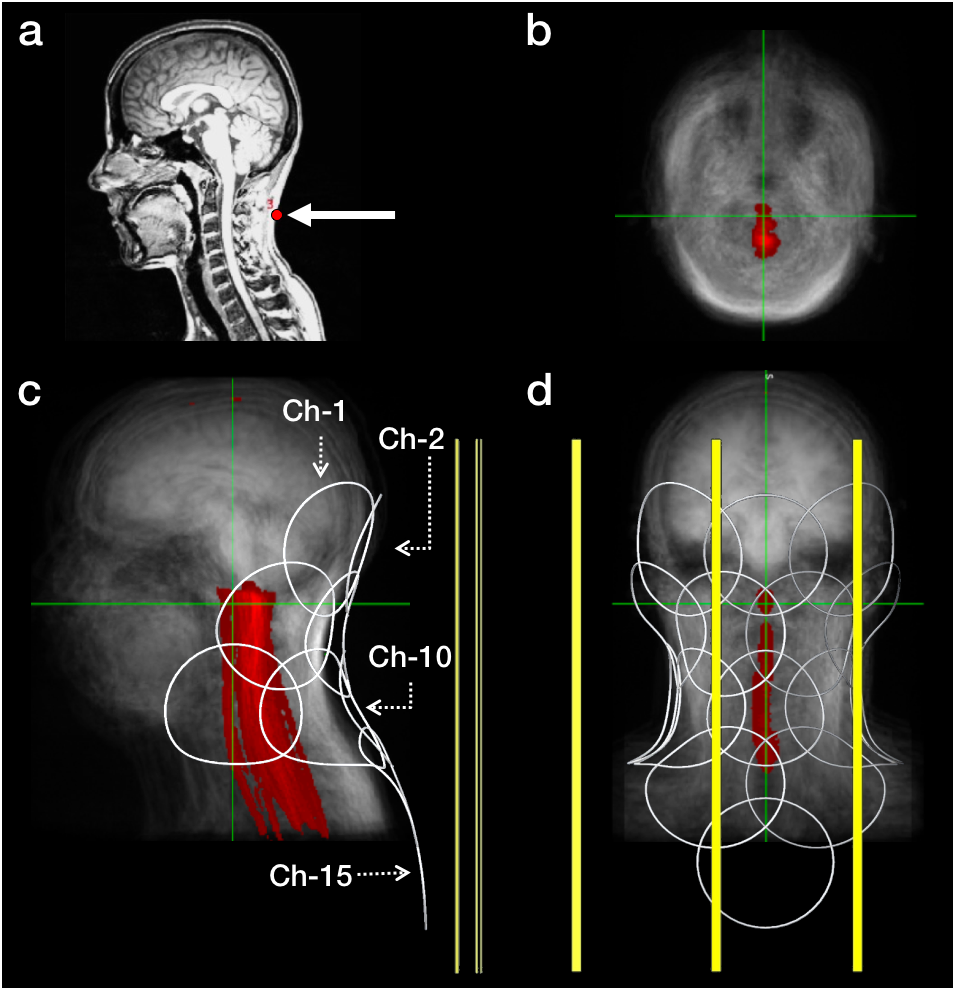
The design was based on T1w scans of 22 adult subjects that were averaged after registration by aligning the posterior of the neck (Fig.1).
Tx coil
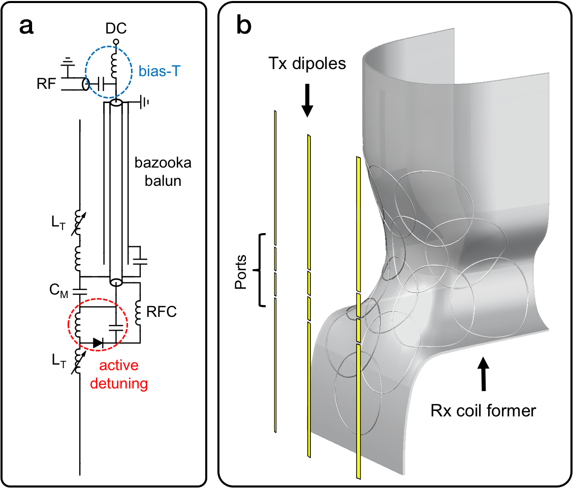
Electric dipoles improve transmit efficiency compared to loop arrays over the spinal region.5 The transmit-coil (Fig.2) consisted of three 38.1cm-long dipoles. Each dipole was inductively shortened to resonate at 297MHz when loaded with the Laura body model in CST. Tuning-matching was accomplished with a co-circuit simulation. The central dipole was located 10.2cm posterior to the centre of the cervical spine. The right and left dipoles were located on a curved surface (radius: 50.6cm) to improve efficiency.
Rx coil
The former of the AC/DC array (Fig.2b) was designed (3D CAD tool) based on the average neck shape from the 22 T1w scans. 15 circular loops were consecutively created in CST by intersecting the former with a 96mm-diameter sphere. Geometric decoupling was achieved by iteratively adjusting the position/diameter of the sphere and running an S-parameters simulation. Tuning, matching and preamplifier decoupling were modeled in the schematic view by adapting published6 circuit schematics. The sensitivity profile of the array was estimated by combining (sum-of-squares) individual B1- maps. A homogeneous sample (permittivity=73, conductivity=1.1S/m) was used in all simulations.
In vivo experiment/Shim simulation
To simulate shim
performance for both static ΔB0
and respiration-induced resonance offsets (RIRO), gradient-echo field maps of
six adult subjects were acquired on a Siemens-3T system with subjects
positioned in the 3D-printed AC/DC
coil former (Fig.2b). Using the body coil in Tx/Rx mode, fields were measured
over inspired and expired breath-hold conditions while a set of bellows
recorded a respiratory signal. Static ΔB0
and RIRO fields in Hz were calculated7 for each subject and scaled by the nominal ratio of the system
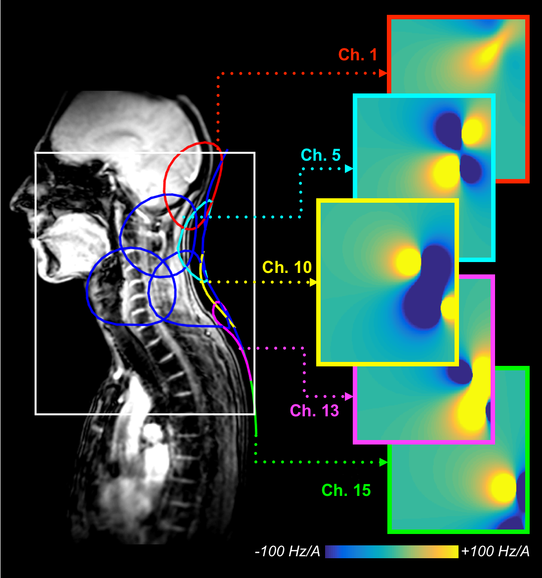
field strengths (7/2.89). Image and CAD coordinates were aligned (Fig.3) and
shim basis fields in Hz/A were computed at the image voxel positions using
Biot-Savart.8 Finally, shim currents (constrained to ≤2.5A per channel) were
optimized for each subject, simultaneously minimizing static ΔB0 and RIRO over a region
encompassing the cervical and upper-thoracic spinal cord. For comparison,
equivalent optimizations were performed using the standard spherical harmonic
basis up to 2nd order.
Results and discussion
Tx coil
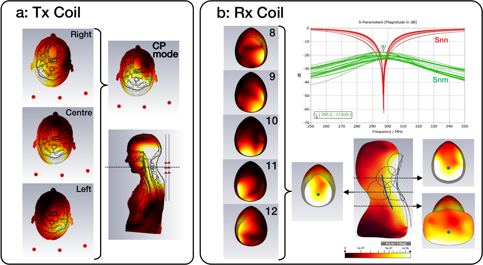
The simulated B1+ profile, in circularly polarized (CP) mode, showed ~50% variation from the occipital lobe to T4 (Fig.4a). The transmit efficiency (per max 10-g SAR) of the CP mode, 0.27µT/√(W/kg), was 18% higher than that of the centre dipole in isolation (0.23µT/√(W/kg)); the commensurate transmit power efficiency in the centre of the cervical spine was 55nT/V. The interplay between the transmit uniformity and SAR efficiency can be adjusted through B1+ shimming. The simulated maximum coupling between adjacent dipoles was 10dB. This topology provides a practical solution to be used with receive-only coils.
Rx coil
Geometric decoupling levels ≤-17.6dB were obtained with all loops tuned and matched to 50Ω (Fig.4b). A maximum increase of 2.4dB was observed when compared to simulations with isolated adjacent pairs. The array showed a satisfactory sensitivity in the spinal cord region, with a combined B1- field variation of 27% along a sample spinal cord (blue, Fig.4b).
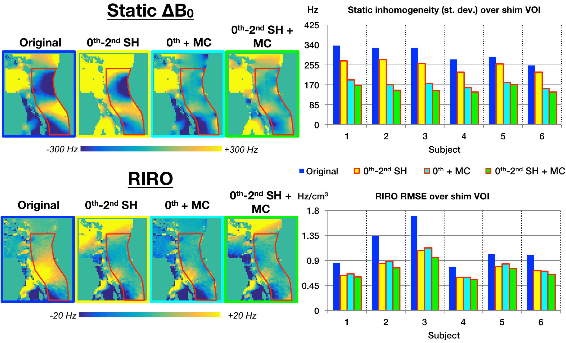
Shimming
Fig.5 summarizes shimming results. Across the shim volume of interest (VOI) and across subjects, the 15-channel array, when combined with a global (0th order) correction reduced the mean static ΔB0 inhomogeneity (i.e. standard deviation) from 253±23Hz using 0th-2nd order spherical harmonics down to 171±14Hz (average improvement: 32±3%). Regarding the RIRO correction, which in Fig.5 is scaled to the standard deviation of the bellows signal as measured over 1min of normal breathing, the two shim bases perform comparably well: Compared to the original RIRO, the 0th-2nd spherical harmonic basis reduced root-mean-square (RMSE) RIRO by 29±6% vs. the 27±6% reduction using the 15-channel array and global offset.
Conclusions
The proposed design can achieve 32% reduction of static field inhomogeneities and 27% reduction in temporal field variance, opening the door to exciting EPI and spectroscopy applications at 7T.Acknowledgements
Funded by the Canada Research Chair in Quantitative Magnetic Resonance Imaging [950-230815], the Canadian Institute of Health Research [CIHR FDN-143263], the Canada Foundation for Innovation [32454, 34824], the Fonds de Recherche du Québec - Santé [28826], the Fonds de Recherche du Québec - Nature et Technologies [2015-PR-182754], the Natural Sciences and Engineering Research Council of Canada [435897-2013], the Canada First Research Excellence Fund (IVADO and TransMedTech) and the Quebec BioImaging Network [5886].References
1. Barry RL, Vannesjo SJ, By S, et al. Spinal cord MRI at 7T. Neuroimage. 2017; 168:437-451.
2. Verma T and Cohen-Adad J. Effect of respiration on the B0 field in the human spinal cord at 3T. Magn Reson Med. 2014;72(6):1629-36.
3. Vannesjo SJ, Miller KL, Clare S, et al. Spatiotemporal characterization of breathing-induced B0 field fluctuations in the cervical spinal cord at 7T S. Neuroimage. 2017;167:191-202.
4. De Leener B, Lévy S, Dupont SM, et al. SCT: Spinal Cord Toolbox, an open-source software for processing spinal cord MRI data. Neuroimage. 2017;145(Pt A):24-43.
5. Duan Q, Nair G, Gudino N, et al. A 7T spine array based on electric dipole transmitters. Magn Reson Med. 2015;74:1189–1197.
6. Stockmann JP, Witzel T, Keil B, et al. A 32-channel combined RF and B0 shim array for 3T brain imaging. Magn Reson Med. 2016;75(1):441-51.
7. Topfer R, Foias A, Stikov N, et al. Real-time correction of respiration-induced distortions in the human spinal cord using a 24-channel shim array. Magn Reson Med. 2018;80:935–946.
8. Lin FH. Magnetic field distributions by Biot-Savart's Law. https://maki.bme.ntu.edu.tw/tools/190-2. Accessed October 4, 2018.
Figures