0215
A target-field shimming approach for improving the encoding performance of a lightweight Halbach magnet for portable brain MRI1Massachusetts Institute of Technology, Cambridge, MA, United States, 2Athinoula A Martinos Center for Biomedical Imaging, Charleston, MA, United States, 3Harvard Medical School, Boston, MA, United States
Synopsis
Portable brain MRI scanners have the potential to increase the reach of diagnostic imaging but require relaxing constraints such as magnet homogeneity and gradient linearity or even elimination of gradient switching via a rotating magnet with built-in encoding fields. Nonetheless, the encoding matrix must retain good conditioning and excessive signal bandwidth must be controlled. To address this, we developed and validated a permanent magnet shimming method for a lightweight Halbach-style brain imaging magnet and designed and constructed a pair of compact, head-only phase encoding gradients. We demonstrate these improvements in spatial encoding with head-sized phantom and in vivo brain images.
Introduction
Portable or point-of-care brain MRI devices have the potential to increase the impact and reach of diagnostic imaging. Several strategies have been introduced to reduce cost and size by relaxing the homogeneity constraints of the main magnet and the linearity constraints of the gradient coils (1–3). Other schemes further eliminate the need for a switching gradient field by using a rotating magnet with a built in encoding field (gradient) (3–5). In all such schemes the encoding matrix must remain well-conditioned. Excessive B0 inhomogeneities also lead to problems with signal bandwidth exceeding that of the detection coils and RF excitation pulses. To address these issues, we developed and demonstrated a novel method of shimming using permanent magnet arrays to improve the built-in readout encoding field of an existing inhomogeneous Halbach-style magnet (2). To improve encoding we also designed and constructed a pair of compact, head-only gradients for in-plane phase encoding and partition encoding (in addition to the built-in readout gradient). We demonstrate these improvements in spatial encoding with head-sized phantom and in vivo brain images.Methods
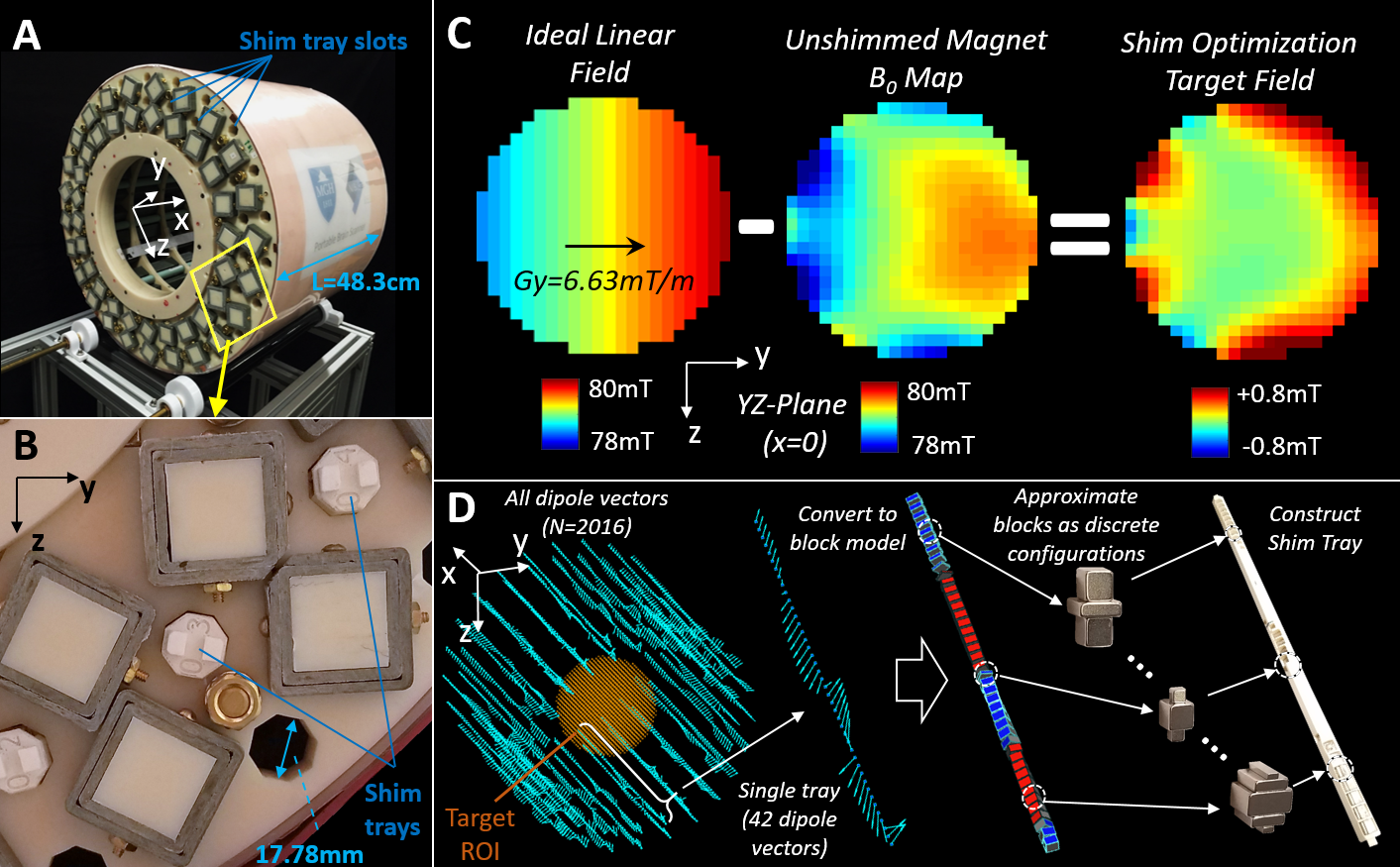
The existing magnet was shimmed using N=48 “shim trays” holding permanent magnet assemblies (Figure 1A,B). Each tray consisted of 42 individual NdFeB magnet configurations spaced 11.025mm apart and fit into an ID=17.78mm octagonal slot. We modeled the N=2016 locations as ideal magnetic dipoles and computed optimal values using a target field approach. The target field (Figure 1C) was the difference of the unshimmed field map and a field with an ideal Gy gradient (6.63mT/m). We minimized: $$$ || D M_{s} - B_{targ} ||_{2}^{2} $$$
Ms is a shim magnet dipole vector and D is the “dipole matrix” that computes the B-field generated at each target point. An initial-guess (Ms,0) was computed using an L2-regularization term. Ms,0 was then used to seed an interior-point optimization (Matlab) with constraints on the maximum dipole allowed (Mmax = a 1.6cm3 N52 block) and requiring that Mx=0 for all dipoles. The calculated dipoles were approximately realized using one of 26 permanent magnet configurations with moments ranging from 0 to Mmax. The magnet configurations were glued into a 3D printed shim tray (Figure 1D).
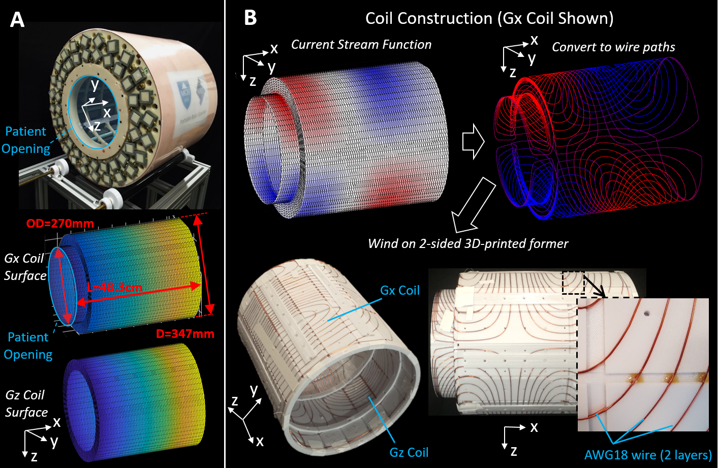
To encode along x and z, two unshielded gradient coils provide in-plane and partition phase encoding blips (Figure 2A). Coil stream functions were optimized to generate linear target fields in a D=21cm spherical target region using a stream function BEM solver (6). These were converted into wire windings (Figure 2B) and constructed by press-fitting 2 layers of enameled AWG18 copper wire into a 3D printed former (Figure 2C). A single coil former held both gradient coils (Gx on the outside and Gz inside.) The shimmed B0 magnet and gradient coils were mapped using a 3-axis hall probe (Metrolab) attached to 3-axis positioning robot.
The RF Tx/Rx used a single-channel helmet-shaped solenoid with a resistively-broadened 3dB BW of 78kHz. A TSE sequence using swept broadband WURST excitation and refocusing pulses was used for imaging (7). Partition (x) encoding occurred down the TSE train and in-plane (z) encoding occurred shot-to-shot. We imaged both an anthropomorphic head phantom and a healthy adult human subject using a shielded patient table to reduce RF interference.
The data was apodized along the readout (y) and in-plane PE (z) dimensions and reconstructed with two image reconstruction schemes: 3D-FFT recon, and a generalized recon that accounted for the nonlinear readout and Gy fields (3).
Results
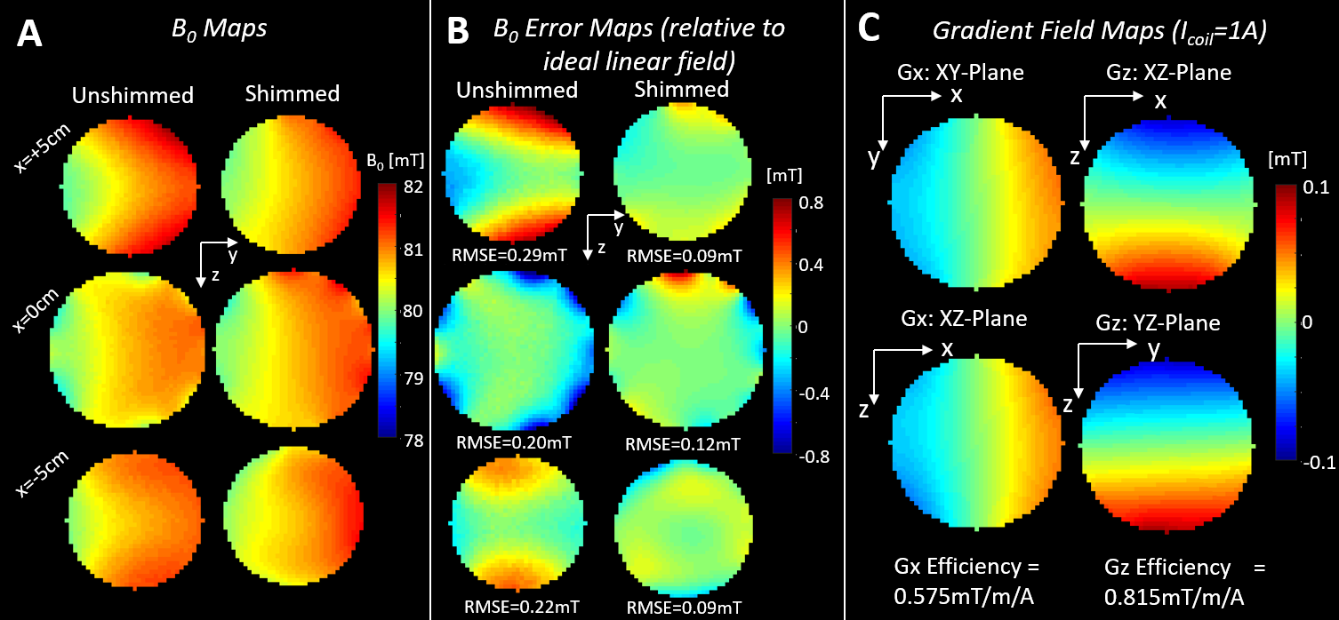
Figure 3A shows the spatial B0 maps before and after shimming. Figure 3B shows the residuals relative to the ideal linear field. Over the target ROI, shimming reduced the RMSE of the residual from 0.27mT to 0.13mT. Figure 3C shows gradient coil field maps at 1 Ampere with coil efficiencies of 0.575[mT/m/A] (Gx) and 0.815[mT/m/A] (Gz).
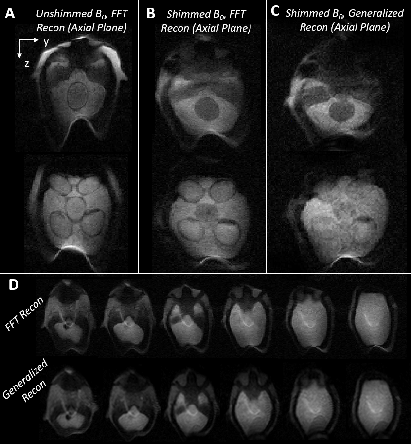
Head phantom images acquired with and without shim trays are shown in Figure 4 these had TE=10ms and TA=7min. Both the shim trays and the generalized reconstruction reduced image distortion.
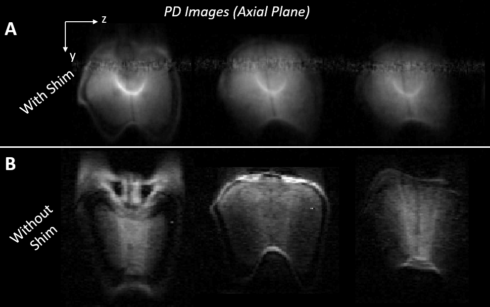
In vivo proton-density (PD) (TE=10ms; TA=14min) are shown in Figure 5. The shim trays reduced spatial distortion and several structures could be resolved in these images. Increased RF interference resulted in banding artifacts and a higher noise floor for in vivo acquisitions.
Discussion
We here demonstrate improved spatial encoding and image reconstruction using a portable, 80mT scanner by using target field shimming and close-fitting blipped gradient coils. The chief remaining challenges for in vivo imaging are reducing RF interference and improving Rx coil performance. Reducing interference requires improved patient shielding and/or interference cancellation, while improving Rx coil performance requires non-resistive Q-lowering strategies.Acknowledgements
NIH: 5T32EB1680, R01EB018976References
1. Vaughan JT, Wang B, Idiyatullin D, Sohn S, Jang A, BelaBarra L, Garwood M. Progress Toward a Portable MRI System for Human Brain Imaging. In: ISMRM. ; 2016. p. 498.
2. Cooley CZ, Haskell MW, Cauley SF, Sappo C, Lapierre CD, Ha CG, Stockmann JP, Wald LL. Design of Sparse Halbach Magnet Arrays for Portable MRI Using a Genetic Algorithm. IEEE Trans. Magn. 2017.
3. Cooley CZ, Stockmann JP, Armstrong BD, Sarracanie M, Lev MH, Rosen MS, Wald LL. Two-dimensional imaging in a lightweight portable MRI scanner without gradient coils. Magn. Reson. Med. [Internet] 2015;73:872–83. doi: 10.1002/mrm.25147.
4. Bluemler P. Proposal for a Permanent Magnet System with a Constant Gradient Mechanically Adjustable in Direction and Strength. Concepts Magn. Reson. Part B 2016;46B:41–48. doi: 10.1002/cmr.b.
5. Sarty GE. Cyclic generalized projection MRI. Magn. Reson. Imaging [Internet] 2015;33:304–311. doi: 10.1016/j.mri.2014.12.006.
6. Bringout G, Gräfe K, Buzug TM. Performance of Shielded Electromagnet-Evaluation Under Low-Frequency Excitation. 2015;51:2–5.
7. Stockmann JP, Cooley CZ, Guerin B, Rosen MS, Wald LL. Transmit Array Spatial Encoding ( TRASE ) using broadband WURST pulses for RF spatial encoding in inhomogeneous B 0 fields. J. Magn. Reson. [Internet] 2016;268:36–48. doi: 10.1016/j.jmr.2016.04.005.
Figures