0214
Initial imaging experience with a head gradient (MAGNUS) at 3.0T operating at 200 mT/m and 500 T/m/s1GE Global Research, Niskayuna, NY, United States, 2GE Healthcare, Florence, SC, United States, 3Walter Reed National Military Medical Center, Bethesda, MD, United States, 4Uniformed Services University of the Health Sciences, Bethesda, MD, United States, 5Ft. Belvoir Community Hospital, Ft. Belvoir, VA, United States
Synopsis
Healthy volunteer subjects were safely imaged in a 3.0 T MRI system with an ultra-high performance head-gradient coil. The MAGNUS coil operates at 200 mT/m and 500 T/m/s, simultaneously on all 3-axes, and has a patient (head) bore diameter of 37-cm. Substantial reduction in pulse sequence TE, TR, and echo-planar imaging echo spacing was achieved with observable improvement in image quality. The design enabled the achievement of higher peripheral nerve stimulation thresholds compared to that for whole-body gradient coils.
Purpose
Slew rate in whole-body gradient coils is typically limited to a maximum of 200 T/m/s by peripheral nerve stimulation (PNS). However, gradient amplitudes on the order of 200-300 mT/m are needed for improved brain microstructure connectivity [1], and slew rates >500 T/m/s are essential for improved functional connectivity [2]. Smaller, head-sized gradient coils can achieve substantially higher slew rates because of 2-3x higher PNS thresholds [3-6]. The Compact 3T (C3T) scanner [5], achieves a slew rate of 700 T/m/s and Gmax of 80 mT/m using a 1 MVA driver. In comparison, the Connectome gradient [1] achieves 300 mT/m using an 8 MVA driver but its slew rate of 200 T/m/s is no higher than a whole-body clinical MRI system. Initial in-vivo results using the 42-cm inner diameter MAGNUS gradient coil that can simultaneously achieve 200 mT/m with 500 T/m/s [7] is described.
Methods
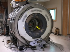
The MAGNUS
gradient coil was installed in a whole-body 3T (WB3T) MRI (GE SIGNA MR750). A custom patient bore tube (“trumpet”)
(Figure 1) was used to mount the RF shield and 16-rung birdcage RF coil. With the same form factor as the C3T gradient,
the PNS limits of the rheobase and chronaxie time were set to 52.2 T/s and 611 μs, respectively.
Acoustic measurements were made using a Brüel & Kjaer Model 2250 sound level meter. Imaging protocols used for testing the C3T system [8] were used for measuring the peak (dB) and A-weighted (dBA) sound pressure levels (SPL). The sequence TE and TR times were compared to that of WB3T MRI, and also the C3T scanner. A 32 -channel head coil (NOVA Medical, Wilmington, MA) and a standard 8-channel brain coil were used in all experiments. Four healthy volunteers (3 males, 1 female; mean mass = 76 +/- 11 kg, and mean age = 44 +/- 9 years) were consented and scanned under IRB-approved protocols.
Results
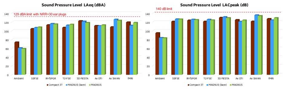
Figure 2 shows the results of the acoustic SPL tests at full amplitude and slew rate (200 mT/m and 500 T/m/s). Initial measurements were made with progressive addition of acoustic treatments to remain within safe operating limits with hearing protection: 99 dBA without hearing protection, and 140 dB peak. When compared with the C3T system (80 mT/m and 700 T/m/s), the mean SPLs were about 3 dBA and 3 dB higher for the A-weighted and peak levels, respectively. Additional acoustic treatments are being pursued to reduce the noise level further.
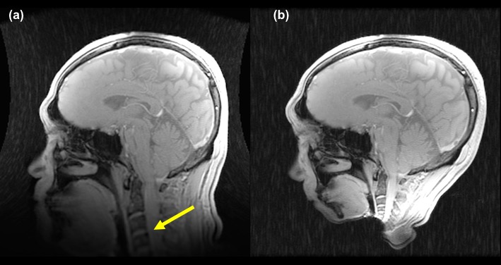
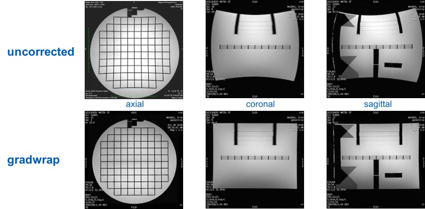
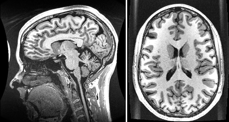
In terms of spatial coverage, across the four volunteers, the cervical spine C4/C5 junction was well visualized without distortion in a 26-cm FOV (Figure 3) after correction for gradient non-linearity using 10th order 3D spherical harmonic correction [9]. As such, the pre-frontal cortex and the cerebellum are well visualized without distortion. In addition, as seen in Figure 4, gradient non-linearity was well corrected in the axial, sagittal, and coronal planes as seen with the ACR phantom. For all subjects, the scans were well tolerated with 2 of 4 subjects reporting mild but not painful sensation in the area of the face.
In Figure 5, 3D-MPRAGE images demonstrate
clear depiction of the anatomical structures and qualitatively appear to be
sharper than those acquired in whole-body MRI systems, as previously observed using
the C3T scanner [5]. With higher performance gradients, the MPRAGE TR for a 1-mm isotropic acquisition was reduced 10%
from 6.1 ms to 5.5 ms compared to the C3T scanner, and reduced 25% compared to WB3T
MR (from 7.4 ms). The reduction in TR resulted in a sharper point spread
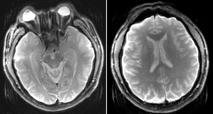
function for the FGRE readout. Figure 6
shows a SE-EPI image that has reduced geometric distortion and
signal drop-off compared to WB3T MRI. This was the result of the
echo spacing reduced from 856 μs to 508 μs. Cusp-artifact (“Annefact”)
[10] was noted only in the MPRAGE images. The artifact was minimal and did not affect any part of the brain.
Discussion
Initial results with the MAGNUS gradient demonstrated marked reductions in TE, TR, and echo spacing compared to WB3T and even to the C3T in some instances. At the maximum gradient amplitude and slew rate, the acoustic noise level was only slightly above that of the C3T scanner even though the gradient amplitude was 2.5x higher. The clearest advantage of the MAGNUS gradient is in high b-value DTI (b=10,000 s/mm2) where the TE was reduced from 109.5 ms in WB3T, and from 76.7 ms in C3T, to 49.4 ms for MAGNUS. This emphasized the importance of high slew rate and high maximum gradient amplitude that allows both substantially improved structural connectivity imaging as well as functional connectivity imaging, all in a gradient that can be easily installed in any clinical 3T scanner.Acknowledgements
Funding support: CDMRP W81XWH-16-2-0054. The opinions or assertions contained herein are the views of the authors and are not to be construed as the views of the U.S. Government or Department of Defense.References
1. Setsompop K, et al. Neuroimage 2013; 80: 220-33.
2. Feinberg D, et al. Neuroimage 2017; 164: 155-63.
3. Lee SK, et al. Magn Reson Med 2016; 76: 1939-50.
4. Tan ET, et al. J Magn Reson Imag 2016; 44: 653-64.
5. Foo TKF, et al. Magn Reson Med 2018; 80: 2232-45.
6. Weiger M, et al. Magn Reson Med 2018; 79; 3256-66.
7. Foo TKF, et al. Proc. 26th ISMRM, p. 839.
8. Weavers PT, et al. Med Phys 2016; 43: 1259-64.
9.
Tao S,
et al. Phys Med Biol 2017; 62:
N18-31.
10. Rangwala N, et al. Magn Reson Med 2010; 64: 220-8.
Figures