0212
Design of a volume MRI coil by metalyzing 3D printing substrates by electroless and/or electroplating processes1Univ. Lyon, INSA-Lyon, Université Claude Bernard Lyon 1, UJM-Saint Etienne, CNRS, Inserm, CREATIS, Lyon, France, 2Univ. Claude Bernard Lyon 1 (UCBL) Laboratoire AMPERE UMR 5005 CNRS, INSA, ECL, UCBL Campus LyonTech - La Doua, Lyon, France
Synopsis
Manufacturing compact, miniature devices required for small samples imaging is still challenging. Here we investigate the feasibility of metalyzing 3D printing subtrates to develop a volume coil dedicated to both small in-vitro / ex-vivo samples and in vivo mouse brain imaging. In order to validate the use of metalized 3D printed process to build MRI coil we build one reference Helmholtz coil made with copper tape wrapped around the coil mount and one with the same geometry using this new technology. First demonstration on bench and in imaging that copper metallization technology can be performed to build volume coil.
Introduction
The performances of clinical MR-machines are not fully available on preclinical MRI. The main reasons come from the reduced market size of preclinical compared to human MRI and the technological challenges for the manufacturing of compact, miniature devices required for small samples imaging1. As a consequence preclinical MR-instrumentation lags behind the clinical ones. Recently a new manufacturing process has been reported in the literature to build flexible coils to improve coil fit specially in children imaging2,3. The coil is screen-printed in 2D on flexible substrate and bended on the sample. In addition it has been shown that 3D printing technology can help to design easy to handle MRI set up that integrate multiple components: the MRI coil, the anesthesia and a multipart mouse fixation4. In preclinical MRI there is often need to combine 3D rigid parts which implies that the metal must be deposit directly on non-planar surface as already reported in reference 5. Here we investigate the feasibility of metalyzing 3D printing subtrates to develop a volume coil dedicated to both small in vitro / ex vivo samples and in vivo mouse brain imaging.Material and Method
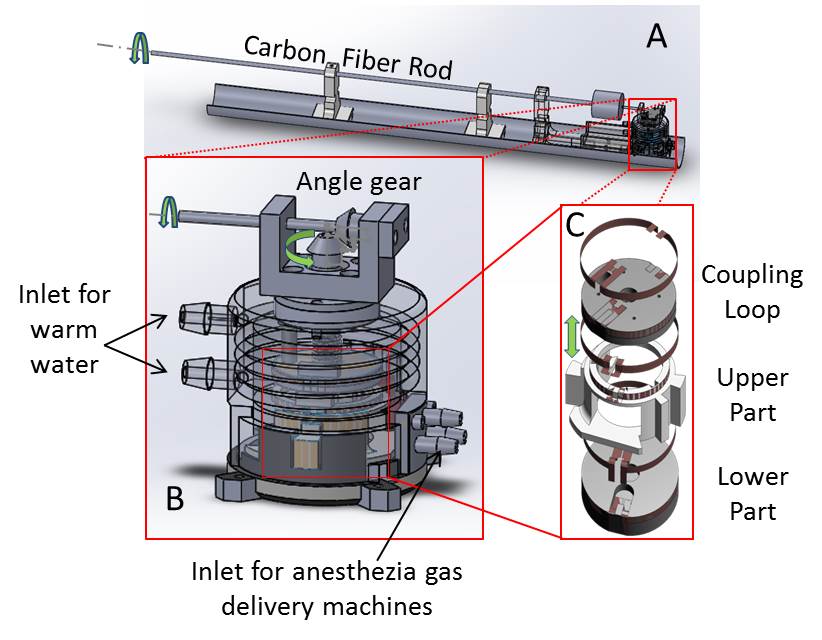
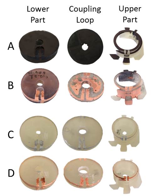
In order to validate the use of metalized 3D printed process to build MRI coil we build one reference Helmholtz coil made with copper tape wrapped around the coil mount and one with the same geometry using this new technology. The coil is inductively coupled to the reception channel using a coupling loop and its distance to the coil can be adjusted to match the coil to 50Ω with a mechanical shaft monitored outside the bore of the MRI magnet (Figure 1). The coil mount was 3D printed using stereolithography process (Form 2 printer - Formlabs) with high temperature resin. To metalize the 3D printed parts, two approaches were used: in the first one, copper plating by Electroless deposition was used after applying Palladium colloids catalyst on the surface to metalize; copper electroplating was then applied to increase the copper thickness. In the second method, silver ink was applied on the parts to metalize, following by copper electroplating metallization (Figure 2). Each element of the Helmholtz coil was tuned in order to have the pair resonating at the Larmor frequency. The coupling loop was also tuned at the larmor frequency.
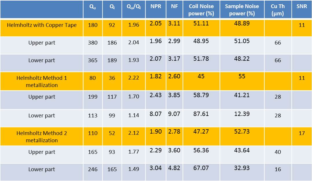
Different characterizations of the coil have been performed on bench. First, unloaded (Qu) /loaded (Ql) quality factor were measured using the single loop probe method6. As introduced in 7, loop efficiency (Qu/Ql), noise power ratio (NFR) and noise figure of the coil (NF) were derived. NF measures the Signal to Noise Ratio (SNR) decrease attributable to losses in the coil which means that lossless coil has NF=0. Thus, this parameter is beneficial to study the quality of our manufacturing process to build coils. Second, thickness of deposited copper was measured using X-ray fluorescence (Bowman). Third, Qu and Ql of the assembled Helmholtz coil were measured connecting the coupling loop to a network analyzer.
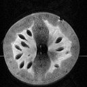
The different coils were characterized in imaging conditions on a 4.7T magnet. SNR measurements were performed on images of an agarose gel acquired with a 3D Flash sequence with the following parameters: matrix 128×128×64, FOV 25×25×25, i.e. spatial resolution of 195×195×391µm3, TR 15ms, TE 6ms which lead to a total acquisition time of 2 min 2 s. One T2-weighted RARE acquisition was performed on a tomato to serve as an illustration with the following parameters: matrix 128×128, 30 0.4mm-thick slices, FOV 25.6×25.6, i.e. spatial resolution of 200×200×400µm3, TR 8000ms, TE 30ms, Average 4, Acquisition time 8 min (Figure 3).
Results
Table 1 summarizes the radiofrequency characterization and deposited-copper thickness measurements. Qu of the element made with copper tape were higher than the ones made with the two metallization methods described above. Not surprisingly coil made with the second method had higher Qu than coils made with the first one, due to the higher copper thickness which increases conductivity. Sample losses were higher than coil losses for the three Helmholtz coils which leads almost to same SNR in imaging.Discussion and conclusion
First demonstration on bench and in imaging condition that copper metallization
technology can be performed to build 3D volume coil. Compared to other
technologies reported in the literature to deposit conductive parts on
polymers, it seems that our technology could lead to higher Qu. The
fabricated coil integrates a mechanical actuator, a fluidic monitoring
temperature of the sample and anesthesia inlets for in vivo imaging: this
device is perfect to provide a continuum assessment of mouse brain from in
vitro to in vivo stage using MRI.Acknowledgements
This work was founded by PIA and Fondation pour l'Université de Lyon and performed within the framework of the labex PRIMES (ANR—11-LABX-0063). We want to acknowledge The PILoT facility for the support provided on image acquisition.References
[1] F. D. Doty, G. Entzminger, J. Kulkarni, K. Pamarthy, and J. P. Staab, ‘Radio frequency coil technology for small-animal MRI’, NMR Biomed., vol. 20, no. 3, pp. 304–325, May 2007.
[2] J. R. Corea et al., ‘Screen-printed flexible MRI receive coils’, Nat. Commun., vol. 7, p. 10839, Mar. 2016.
[3] D. Mager et al., ‘An MRI Receiver Coil Produced by Inkjet Printing Directly on to a Flexible Substrate’, IEEE Trans. Med. Imaging, vol. 29, no. 2, pp. 482–487, Feb. 2010.
[4] K.-H. Herrmann, C. Gärtner, D. Güllmar, M. Krämer, and J. R. Reichenbach, ‘3D printing of MRI compatible components: Why every MRI research group should have a low-budget 3D printer’, Med. Eng. Phys., vol. 36, no. 10, pp. 1373–1380, Oct. 2014.
[5] T. Matsunaga et al., ‘Multilayered receive coil produced using a non-planar photofabrication process for an intraluminal magnetic resonance imaging’, Sens. Actuators Phys., vol. 261, pp. 130–139, Jul. 2017.
[6] J.-C. Ginefri, E. Durand, and L. Darrasse, ‘Quick measurement of nuclear magnetic resonance coil sensitivity with a single-loop probe’, Rev. Sci. Instrum., vol. 70, no. 12, pp. 4730–4731, Dec. 1999.
[7] A. Kumar, W. A. Edelstein, and P. A. Bottomley, ‘Noise figure limits for circular loop MR coils’, Magn. Reson. Med., vol. 61, no. 5, pp. 1201–1209, May 2009.
Figures