0069
Intra echo train correction for constant flip angle Turbo Spin Echo sequence1Department of Radiology, Medical Physics, Medical Center University of Freiburg, Faculty of Medicine, University of Freiburg, Freiburg im Breisgau, Germany
Synopsis
Turbo spin echo (TSE) sequence is one of the “workhorses” used in routine clinical applications for MR imaging [1]. However, long scan time and segmented k-space acquisition make it particularly susceptible to
Introduction
There are several technics developed to reduce motion artifacts prospectively like ones based on optical tracking [2]. However, no intra-echo train correction has been used routinely for TSE. One of the possible reasons is that due to noise in motion tracking data, signal coherence can be destroyed resulting in a signal intensity drop, even if imaging a stationary object.
In this work, we present an analysis linking tracking noise to the signal drop based on extended phase graph (EPG) simulation [3]. Sequence optimization approaches are proposed to compensate for signal drop due to tracking noise in intra-echo train correction for constant flip angle TSE sequences.
Theory
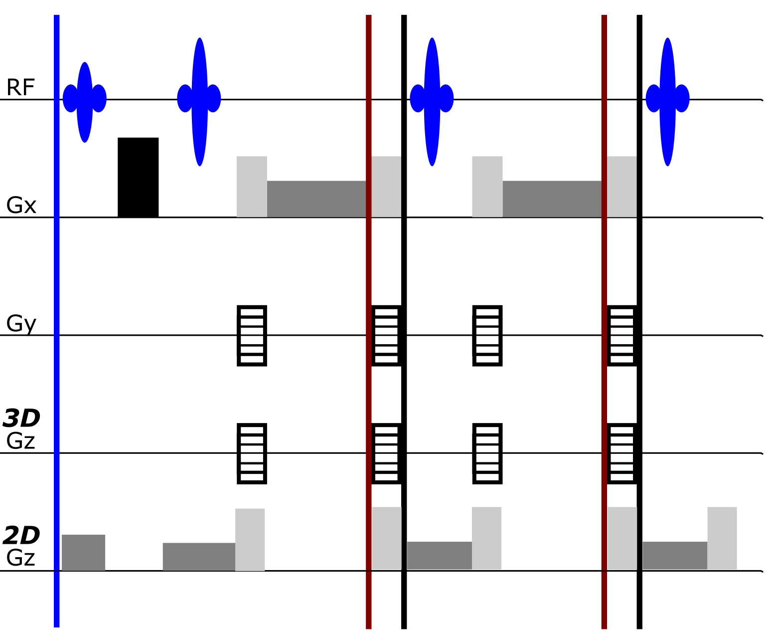
As seen in Fig. 1 the echo-train correction is applied after the readout gradient at a k-space position at the periphery or well beyond the nominal k-space extent. Small errors in rotation in this case prevent a correct rephrasing in the next inter-echo interval. Ignoring noise in readout pre-phasing, accumulated phase from readout gradient due to rotation noise could be depicted as:
$$ φ(n+1)=φ(n)+∆φ(n) (1)$$
$$∆φ(n)=w(n)*M*P (2)$$
Due to (1) and (2),
$$φ(n+1)=∑_1^n w(n) *M*P (3)$$
Here, φ(1) = 0; n=1,2,3…N echo. w(n) is rotation noise relative to the original position at the nth echo. M is the gradient moment in the readout direction, and P is the object position. These phase contributions can be understood as RF phase error in EPG expression, which will break CPMG condition and induce signal drop from the desired signal intensity.
Therefore, if within the echo train more echoes maintain their phase relations, pseudo-CPMG condition could be partly preserved, so is the signal intensity. We term the approach of freezing the correction for some cycles a Frame Share (FS). Alternatively, gradient moment M at the time point of correction can be reduced by placing this point right before the post-readout dephaser. We name this approach Effective MOtion COrrection (EMOCO). Fig. 1 indicates possible positions for motion correction between echo trains, during echo train without and with EMOCO.
Methods
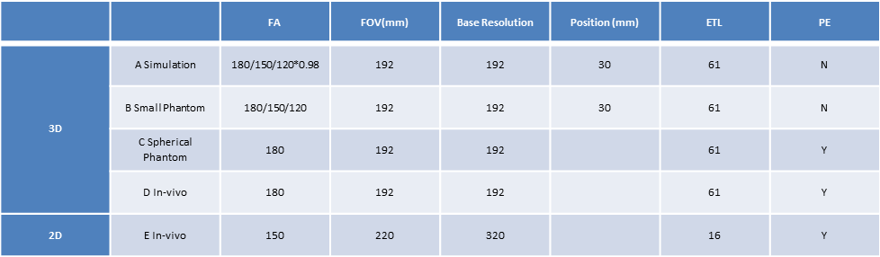
As shown in Table 1, simulations and MR measurements were performed with simulated random navigator noise (std=0.02°). Small phantom (height 10mm, radius 2.5cm) without phase encoding was used in MR measurement to compare with simulation results. Sphere phantom and in-vivo measurement were presented to show the signal intensity behavior in image domain. During in-vivo measurement, subjects were asked to keep as still as possible.
For simulation, EPG (T1/T2 400/200 ms; position: 3 mm off-center; FA bias 2%) with random noise were simulated in Matlab (2016a, The MathWorks, Natick, MA, USA). All MR measurements were executed on 3T Magnetom Prisma system (Siemens Healthcare, Erlangen, Germany) with modified 3D/2D TSE sequences. Random noise input and sequence synchronization were achieved by XPACE library [4].
Results & Discussion
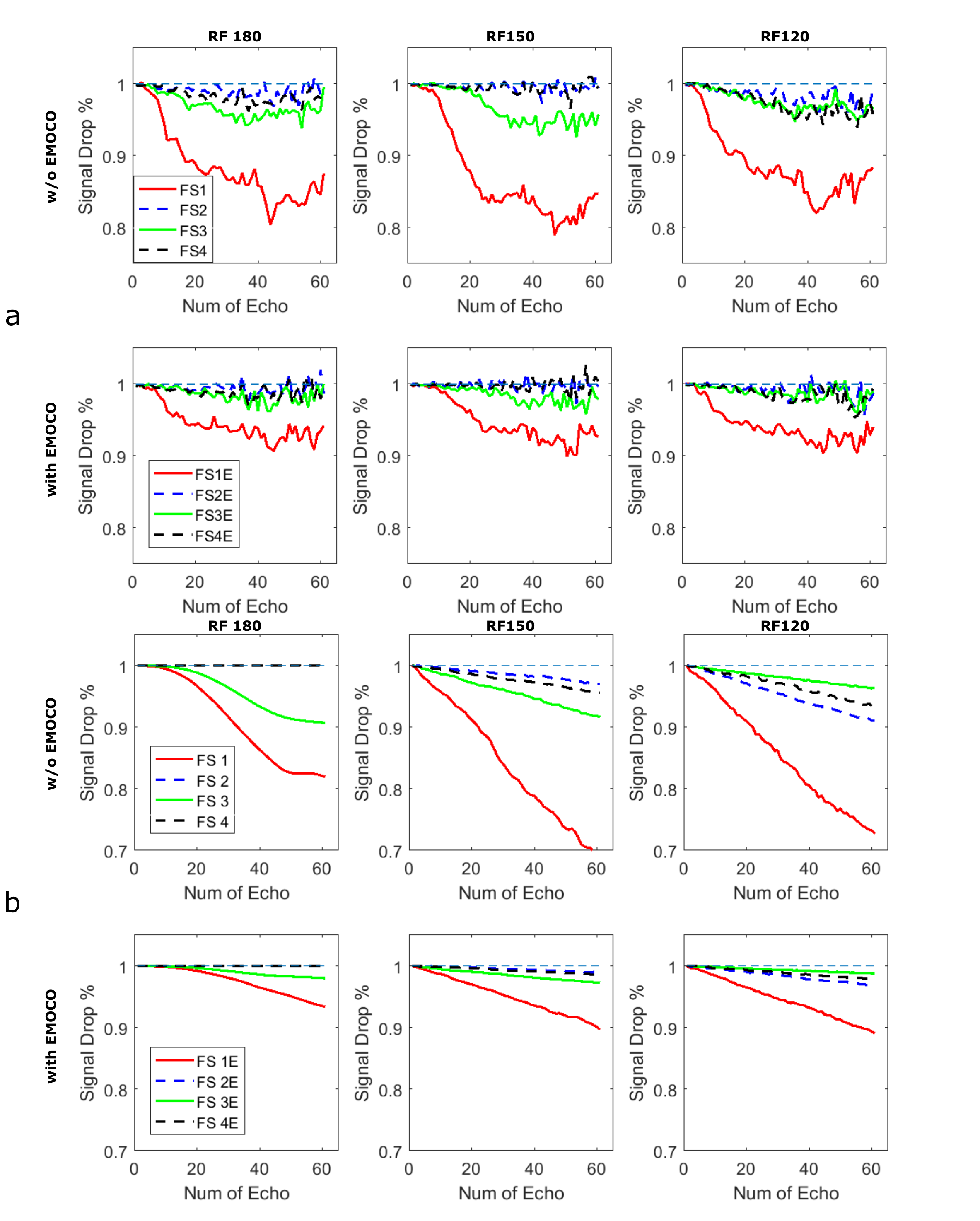
Fig. 2 shows signal drop in small phantom based on simulation and MR measurement. For high constant flip angle schedules (>135°), the effect of dephasing transverse magnetization was dominant. By adjusting coordinate only for every even echoes, like FS2 and FS4, RF phase error accumulation was dramatically reduced and thus pseudo-CPMG condition was close to CPMG condition, which mitigates a signal drop significantly. Upon a decrease of refocusing flip angle, the balance between the low and high order dephasing states in the phase graph shifts towards high orders which progressively wipes the differences between FS modes. Considering T1 relaxation, B0/B1 inhomogeneity and other system imperfections, simulations and experimental results match closely. As expected with no phase encoding EMCO could preserve signal intensity significantly better than other options.
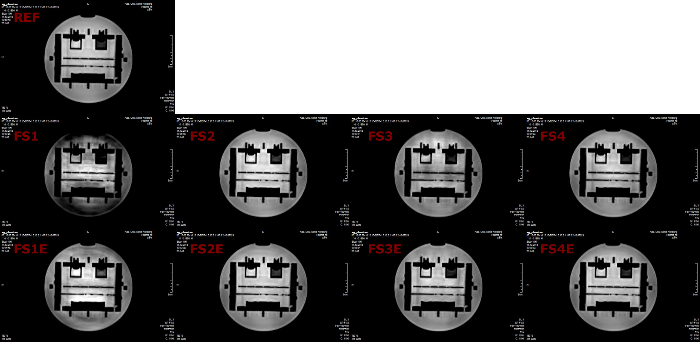
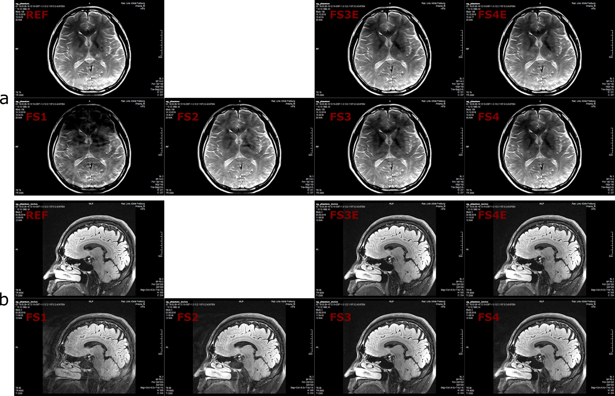
Spherical phantom (C) and In-vivo (D) measurements within 3D TSE sequence are presented in Fig. 3 and Fig. 4a, respectively. FS2 and FS4 showed a higher image intensity compared to FS1 and FS3. EMOCO could further enhance signal amplitude and suppress artifacts. FS1 showed strong signal attenuation and artifacts.
2D high resolution in-vivo imaging is shown in Fig. 4b. Due to the imperfection of the 2D slice profile, the bias from the desired FA is larger than 3D. With the increasing percentage of high order dephasing states, spin echo was not dominant anymore; hence FS3 presented best signal intensity. By using EMOCO, image quality for FS3E and FS4E was further enhanced. Therefore, in practice FS4 with EMOCO is considered to be the best option for performing prospective intra-echo train motion correction in constant flip angle TSE sequences.
Our optimization predicts that intra-echo train motion correction with the available optical tracking system is feasible.
Acknowledgements
No acknowledgement found.References
1. Hennig, J., A. Nauerth, and H. R. A. R. E. Friedburg. "RARE imaging: a fast imaging method for clinical MR." Magnetic resonance in medicine 3.6 (1986): 823-833.
2. Gao, X., Amrein. P, et al. "Ultra-High-Resolution Dental MR Imaging Using an Ultra-Short-TE Sequence with Prospective Motion Correction" In Proceedings of the 26th Annual Meeting of ISMRM 2018
3. Weigel, Matthias. "Extended phase graphs: dephasing, RF pulses, and echoes‐pure and simple." Journal of Magnetic Resonance Imaging 41.2 (2015): 266-295.
4. Zaitsev, Maxim, et al. "Magnetic resonance imaging of freely moving objects: prospective real-time motion correction using an external optical motion tracking system." Neuroimage 31.3 (2006): 1038-1050.
Figures