0066
Wireless motion tracking with short-wave radiofrequency1Institute for Biomedical Engineering, University and ETH Zurich, Zurich, Switzerland
Synopsis
For robust and high-quality brain imaging rigid body motion correction plays an increasingly important role.
We propose a wireless motion tracking method based on short-wave RF signal transmission that does not require a direct line of sight and can penetrate tissue and plastics between detector and marker providing a unprecedented degree of freedom in marker placement and fixation. Single digit micrometer precision during an EPI sequence could be demonstrated even at high tracking bandwidth of 100 Hz with minimal latency and operating independently from the scanner.
Introduction
For robust and high-quality brain imaging rigid body motion correction has gain paramount importance. Current methods include: navigators [1], coregistration techniques [2], gradient pickup coils [3], NMR field sensors [4-7] or optical systems with markers [8-12] or without [13]. Hereby markerless methods pose restrictions in precision and/or temporal resolution. Gradient localization based methods require integration into the sequence and cabling running to the subject for highest sensitivity.
While optical methods provide a high degree of independence form the scanner they require a line-of-sight. This is not commonly provided by receiver arrays, especially at UHF. Furthermore, stimulation devices or the subject’s hair can be prohibiting.
Marker-based methods have demonstrated the highest fidelity [14], with marker fixation to the skin being the limiting factor for accuracy unless a bite bar is used. Also, such a bite bar must extend outside of the mouth causing discomfort and requiring a very tight fit to the teeth.
Both marker fixation and the requirement for a line-of-sight hamper for broad application. To address these issues, we propose a novel tracking technique based on short-wave RF signal transmission [15] as depicted in Fig. 1. The marker is a passive wireless RF reflector that scatters an applied RF field towards a detector array. The position is calculated by processing the phase and amplitude of the received signals.
The employed RF field in the low short-wave frequency range can penetrate tissue and plastic housing parts with negligible signal alteration, rendering a line-of-sight unnecessary. This opens new possibilities for fixating the marker, e.g, it can be mounted inside a hearing protection or on teeth inside the mouth. Furthermore, the employed frequency band is not used by the MR scanner. Hence the tracker can operate fully independently.
Methods
Three DDS generate each a sinusoid at 2.3 MHz, 3.1 MHz and 4.2 MHz which are transmitted by a loop to the reflector. The reflector’s loop elements are each resonant a single of those frequencies being selectively retransmitted.
These signals are received by seven, MR compatible broadband antennas and individually demultiplexed to the three carriers resulting in 21 complex valued signals. These 21 signals represent an overdetermined system encoding the 6 degrees of freedom of the marker position.
To retrieve the position out of the sensor signals, a neural network was deployed. Calibration data to train the network was acquired by positioning the reflector with a precision robot (RX60, Staubli, Horgen, Switzerland) shown in Fig. 2. After training of the network, the forward application determining the position from the sensor data is numerically efficient and fast.
Results
Standard deviation of the absolute position error as determined on the robotic testbench on 750 randomly chosen points was (65um, 30um, 75um) and (20mdeg, 18mdeg, 30mdeg) . The evaluation took place in a cube with edge length of 20mm and +- 5 degrees in all rotation axes.
The precision was evaluated with the same setup and yielded (2.8um, 2.1um, 2.7um) and (4.5mdeg, 8.9mdeg, 8.1mdeg) at 26 positions per second.
Fig. 3 shows the tracking precision during an EPI in the scanner monitoring a fixed marker while the antennas are mounted to a standard head coil. Single digit micrometer precision is achieved in agreement with the robotic test bed. Furthermore, the tradeoff between position output rate and precision is depicted. The overall latency of the system was found around 2ms.
In Fig. 4 shows retrospective correction of a position phantom that was moved between scans. Signal averages were calculated with and without correction of recorded translatory motion.
In-vivo images and physiological motion recorded during scanning is shown in Fig. 5. The subject had the marker in her mouth and was fixing it by biting on it.
Discussion and conclusion
A high precision wireless motion tracking method yielding single digit um precision with high update rate, low latency and no line-of-sight requirement is demonstrated. The system can operate fully concurrently and indecently to the MRI sequence. While the high integrateability, free marker placement and low latency make the system well suited for prospective motion correction in clinical as well as highquality research targeted imaging applications, its precision and sampling rate can be used to study the subjects motion as physiological parameter.
As found on the robotic test and in the MRI scanner, the absolute accuracy of the tracker is significantly lower than its precision. We believe that improved calibration and evaluation methods can resolve this issue to a large degree. It has however to be mentioned, that the absolute position accuracy itself does not play a key role in most motion correction approaches since only deviations from the starting position are corrected for.
Acknowledgements
No acknowledgement found.References
1. Vvan der Kouwe AJW, Benner T, Dale AM. Real-time rigid body motion correction and shimming using cloverleaf navigators. Magn Reson Med 2006;56:1019–1032.
2. Cox RW, Jesmanowicz A. Real‐time 3D image registration for functional MRI. Magn Reson Med 1999
3. A. J. van der Kouwe, B. Fetics , D. Polenur , A. Roth and E. Nevo, Real-time prospective rigid-body motion correction with the EndoScout gradient-based tracking system, ISMRM 2009.
4. Ackerman J et al 1986 Rapid 3D tracking of small RF coils Proc. 5th Annual Meeting of ISMRM
5. Ooi M B et al 2009 Prospective real-time correction for arbitrary head motion using active markers Magn. Reson. Med 6. Haeberlin M et al Real‐time motion correction using gradient tones and head‐mounted NMR field probes Magn. Reson. Med.
7. Sengupta S et al Prospective Real Time Head Motion Correction Using Inductively Coupled Wireless NMR Probes Magn. Reson. Med
8. Tremblay M, Tam F and Graham S J 2005 Retrospective coregistration of functional magnetic resonance imaging data using external monitoring Magn. Reson. Med
9. Zaitsev M et al 2006 Magnetic resonance imaging of freely moving objects: prospective real-time motion correction using an external optical motion tracking system Neuroimage
10. Qin L et al 2009 Prospective head-movement correction for high-resolution MRI using an in-bore optical tracking system Magn. Reson. Med.
11. Schulz J et al 2012 An embedded optical tracking system for motion-corrected magnetic resonance imaging at 7 T Magn. Reson. Mater. Phys. Biol. Med
12. Maclaren J et al 2012 Measurement and correction of microscopic head motion during magnetic resonance imaging of the brain PLoS One
13. Benjaminsen C et al 2016 Real Time MRI Motion Correction with Markerless Tracking Proc. 24. Annual Meeting of ISMRM
14. Maclaren J et all 2013 Prospective Motion Correction in Brain Imaging: A Review Magn. Reson. Med.
15. Hansen, PK, Method and apparatus for position and orientation measurement using a magnetic field and retransmission, US4642786
Figures
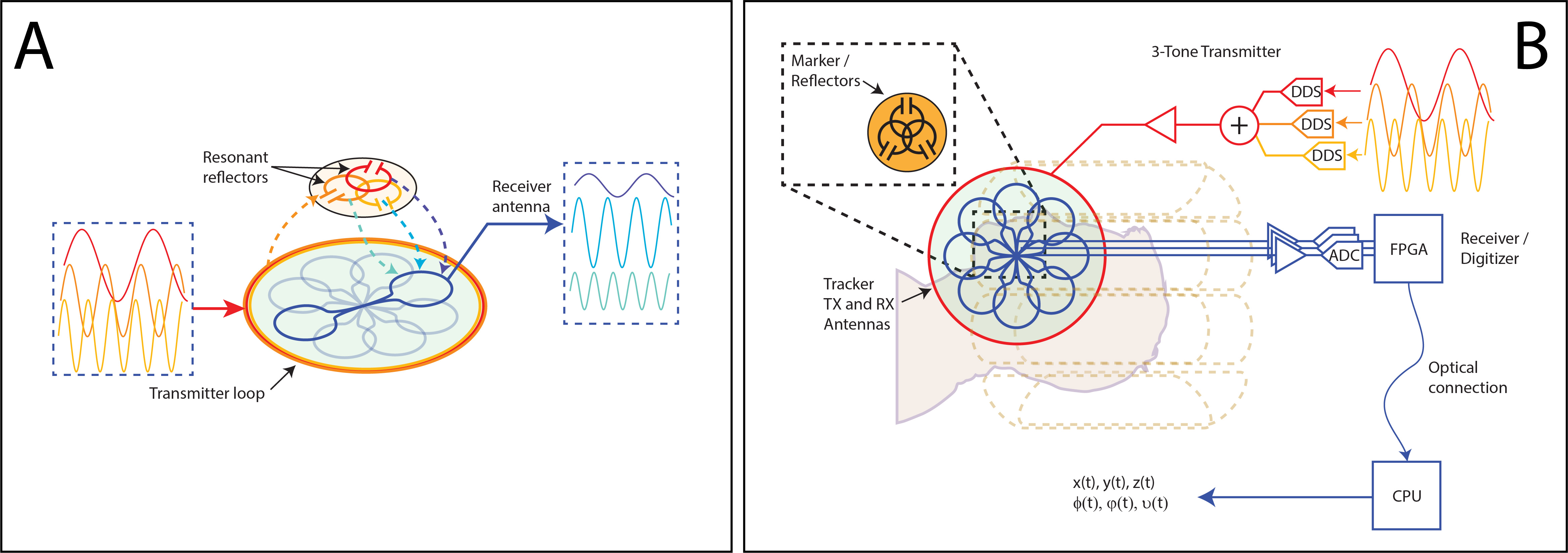
Section A shows the basic principle of the tracker. The marker contains three geometrically decoupled loops which are resonant on three different frequencies. The field generated by the transmitter couples into the marker whose reflectors retransmit it frequency selectively. This retransmission is then measured by an array of receiving antennas. The receiving antennas are constructed as gradiometers such that the direct coupling is supressed.
Section B depicts the schematic of the setup. The signals are generated, digitized and preprocessed in-bore. An optical link broadcasts the data to a computing unit outside the Faraday cage for calculation of the positions.
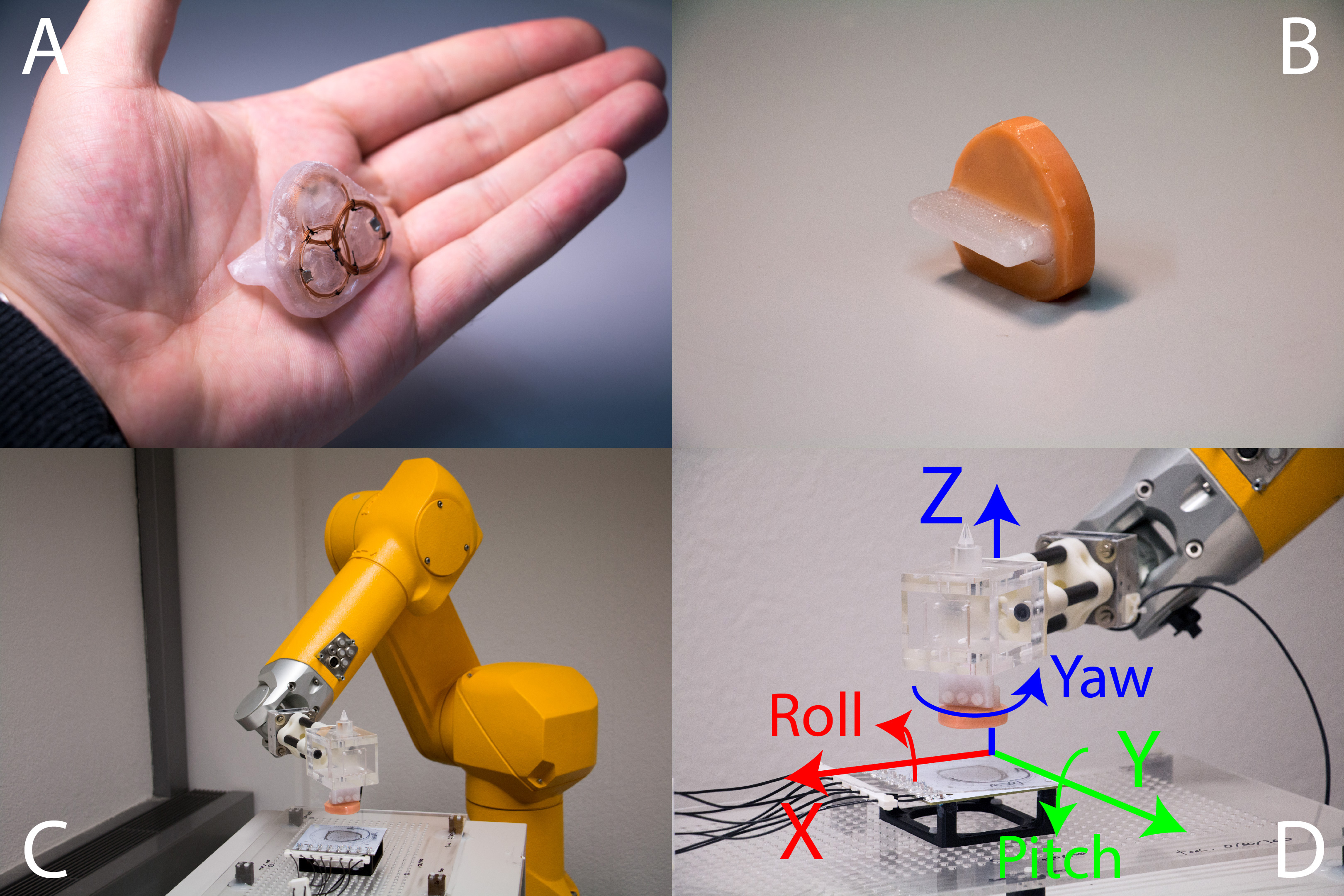
Section A shows the marker. The marker is 3D printed with food grade PET containing the three loops.
Section B shows said marker encapsulated in food grade silicone with the part sticking out that is attached to the teeth.
Section C shows the robotic test bench used to calibrate, test and verify the sensor. On the tool of the robot, a marker is attached.
Section D shows the orientation of the sensor coordinate system
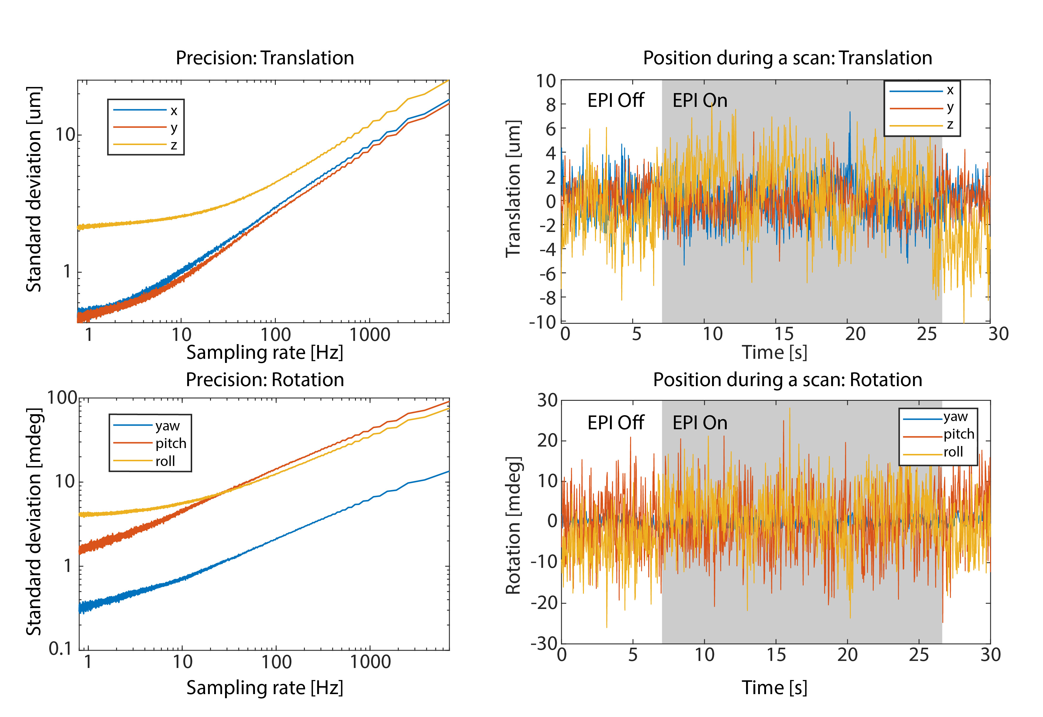
The coordinates in the plots are in the sensor coordinate system (Fig. 2).
On the left show the standard deviation of the detected position vs output rate with a marker attached to a static phantom. The data was recorded during an EPI scan at a reference position. The marker position was in position typically anticipated in the application being roughly in the middle of the receiver array and at a distance of approximately 15mm.
On the right are time series plots of the position recorded at 30 samples per second during an EPI scanning with full gradient duty cycle.
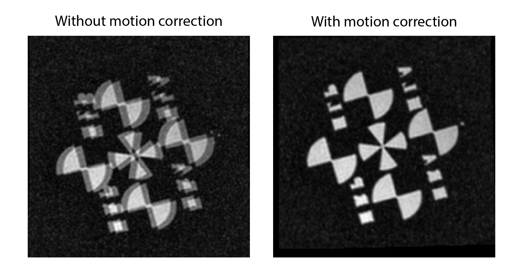
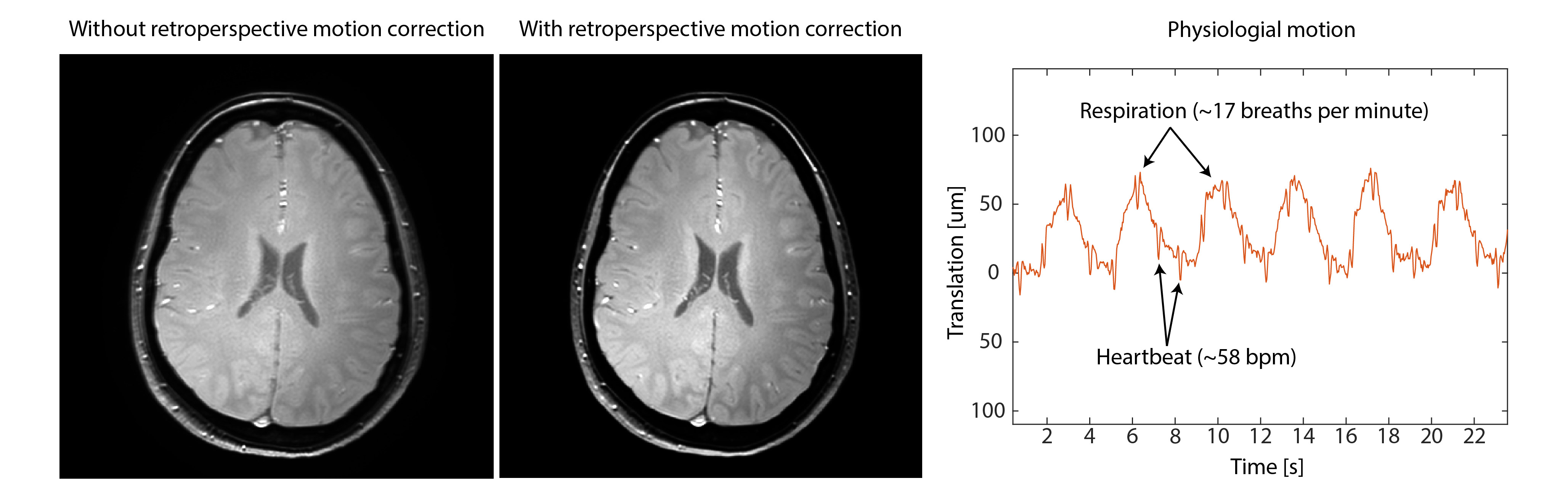
The in-vivo image shows the average of multiple dynamics from a FLASH sequence with small instructed subject motion between dynamics. The dynamics were subsequently averaged correcting for in-plane motion and for comparison without any corrections.
The figure on the right shows the physiological motion during rest. Respiration and the heartbeat are clearly visible.